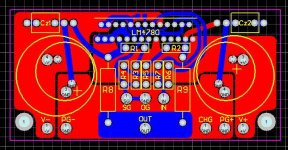
As promised, I did some revisions to the previous layout (mostly cosmetics, with some traces modified). Here's the final layout of amp's board. There is one SMD resistor for muting setting. I think it would be a good idea to provide an extra pad (not neccessarily through hole) for a bigger size resistor, if somebody doesn't want to bother with SMD parts.
Attachments
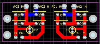
And here's the PS layout. Since that set is high power, parallel configuration, I would imagine that each amps board needs dedicated PS board and it should be offered either as a single set (1 + 1) or stereo set (2 + 2).
The mounting and connection holes are matching and boards can be positioned side by side (vertically)
The mounting and connection holes are matching and boards can be positioned side by side (vertically)
Attachments
Peter Daniel said:And here's the PS layout. Since that set is high power, parallel configuration, I would imagine that each amps board needs dedicated PS board and it should be offered either as a single set (1 + 1) or stereo set (2 + 2).
The mounting and connection holes are matching and boards can be positioned side by side (vertically)
I understand, even if I don't agree with, using thin width on audio passing tracks to avoid stray capacitances. But on a supply pcb?!
Why not filling larger areas for each interconnection between e.g.: D2-D4, D1-D3 and so on? Rectangular blocks would probably do the job fine.
You can also design a single side pcb for the PS, as only one input intercrosses other lines.
Carlos
I don't see much reason to go with single sided board here. PS board will be done together with the amp's board, and since this one is double sided, the PS board can be too.
As to the width of the traces, 100mil is pretty wide, the size of the board is only 1.2 x 2.9 so connections are really short. I don't think anything wider is neccessary, but I also think it wouldn't hurt either.
I'm tempted though to put shielding on one side (connected to mounting holes only) in case rect board is piggy backed with amp's board.
Attachments
Having read this thread since the beginning, I must say I am quite interested in it. One question that has not really been addressed is the VA rating of the transformers that will be used to power these amps. In post # 56 mhennessy came to the concluson that 25 to 28 volt secondaries would be required to power them. Unfortunately, I don't recall reading anything about the VA rating.
I know that Steve of Apex Jr has some 28.4 V at 150 VA Avel-Lindberg toroids so I was wondering if these would work in a dual monoblock configuration. I quite sure they would be under powered for the bridge configuration but would they be OK for the single board configuration ?
I know that Steve of Apex Jr has some 28.4 V at 150 VA Avel-Lindberg toroids so I was wondering if these would work in a dual monoblock configuration. I quite sure they would be under powered for the bridge configuration but would they be OK for the single board configuration ?
Well, I spent some time looking over the LM4780 files, and will get some boards made soon.
Here is a picture of the board, showing both layers and silkscreen:
and a picture of the bottom layer of the pcb:
The pcb is very similar to the size of the LM3875 board, but the amplifier board is a bit bigger. The overall dimensions of the pcb is 2.9" wide by 5.2" deep, compared to the LM3875 board being 4.8" deep.
Any comments on the layout? The recent modifications that Peter and I made are:
- move input wiring a bit farther from the output, and add ground trace in between
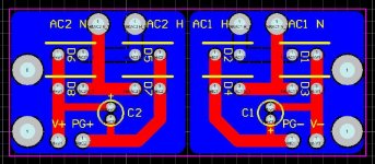
- remove ground plane from rectifier board and restructure a bit
- slight modifications to placement of zobel components.
- increased size of SMD pads for mute resistor to allow a through-hole resistor to easily be soldered in this place.
I am looking to get the boards made soon, after I look over the layout a few more times. I am considering doing a small prototyping run first for testing first.
--
Brian
Here is a picture of the board, showing both layers and silkscreen:
An externally hosted image should be here but it was not working when we last tested it.
and a picture of the bottom layer of the pcb:
An externally hosted image should be here but it was not working when we last tested it.
The pcb is very similar to the size of the LM3875 board, but the amplifier board is a bit bigger. The overall dimensions of the pcb is 2.9" wide by 5.2" deep, compared to the LM3875 board being 4.8" deep.
Any comments on the layout? The recent modifications that Peter and I made are:
- move input wiring a bit farther from the output, and add ground trace in between
- remove ground plane from rectifier board and restructure a bit
- slight modifications to placement of zobel components.
- increased size of SMD pads for mute resistor to allow a through-hole resistor to easily be soldered in this place.
I am looking to get the boards made soon, after I look over the layout a few more times. I am considering doing a small prototyping run first for testing first.
--
Brian
rabstg said:Hey BrianGT-
You said:
"- remove ground plane from rectifier board and restructure a bit"
Why did you remove the ground plane? Does it cause a problem that I am unaware of?
I didn't think that it would be very useful in the way that it was setup, and might possibly pickup more noise then prevent. The recent one that Peter created wasn't tied to anything, and would be tied to ground on the chassis side. I decided that I would rather have the design of the rectifier board to mirror the current LM3875 board, since it seems to work rather well. Notice that I intentionally didn't put wiring for two boards from one power supply board, since the LM4780 will draw more power (should be same as 2xLM3875 boards). The dual-mono configuration will be standard with the kit.
As for a bridging board to go with the kit, I haven't had time to do any prototypes, so I decided to leave it out of the kit. Maybe after a few DRV134 boards have been prototyped, I will add a board for it to the pcb set.
--
Brian
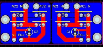
I did one layout with diodes facing back to back and one heatsink plate, but then we discussed with Brian the possibility (and danger) of rectifiers touching each other (when not aligned properly) and creating hazardous situation, especially when the boards are to be used by so many people.
There is still enough room to use two heatsink plates, shared by 4 diodes.
There is still enough room to use two heatsink plates, shared by 4 diodes.
I hope this is the right place for advice on GC kit ideas ")
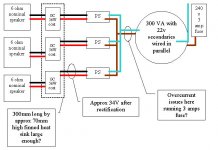
I am considering a 3 channel GC project. I have just ordered the parts and am now planning the layout. However in this planning my ohms law is a little rusty these days, particularly with “VA” ratings which I took to mean Volts*Amps which confuses me on Power which is V*I which is also volts by amps! Anyway I have some questions below and would really appreciate some experienced DIY Amp builder’s input.
I have attached an image with the topology of the setup.
- Can a 300VA tranny successfully run 3 gc amps?
- Is a 300mm long by about 70mm high finned heatsink enough to keep them cool?
- Will the tranny draw more than recommended 3A slow blow fuse?
Using a larger transformer, possibly 400VA is an option but costs will rise (including case requirements). The datasheet for the LM3875 would suggest that 34v post rectified is ok for running 6ohm speakers but was wondering what others experiences were on this.
A picture of the case with its heat sinks (an AKSA kit is being used) is on the link below. Transformer will be the same as seen (if feasible) but naturally the rest will be different, using GC kits from BrianGT. Case example
Attachments
- Status
- This old topic is closed. If you want to reopen this topic, contact a moderator using the "Report Post" button.
- Home
- Group Buys
- Group order of non-inverted LM4780 pc boards? Anyone interested?