Re: shunt resistor
As I explained in the other post, the combination of shunt resistor and the pot shouldn't exceed 22k total value for low DC offset.
Sticking with 22k 'shunt resistor' is safe approach.
xcortes said:sorry if this has already been answered but I can't find it.
I've built two gainclones with 20k stepped attenuators. I'm about to build another as a gift and wan't to use the much cheaper RS 100k pot instead.
The manual shows the connection diagram but also mentiona a "shunt" resistor.
What value would the resistor be for a 100k pot?
Where do I connect it?
Thanks a lot
As I explained in the other post, the combination of shunt resistor and the pot shouldn't exceed 22k total value for low DC offset.
Sticking with 22k 'shunt resistor' is safe approach.
Big thanks to Peter Daniel and Brian
Just to send a big thanks to Peter Daniel and Brian!") I received my lm3875 premium set / pcb this weekend. I have finished the first stereo set.
I received my lm3875 premium set / pcb this weekend. I have finished the first stereo set.
Although I got a humm problem, the bass timing of this amp is impressive. Maybe this is related to the lack of a input cap, which my other gainclone feature.
About the humm, guess I need to re-check my single tranny/dual secunds/ dual mono config...
Thx and best regards,
Thijs
Just to send a big thanks to Peter Daniel and Brian!
I received my lm3875 premium set / pcb this weekend. I have finished the first stereo set. Although I got a humm problem, the bass timing of this amp is impressive. Maybe this is related to the lack of a input cap, which my other gainclone feature.
About the humm, guess I need to re-check my single tranny/dual secunds/ dual mono config...
Thx and best regards,
Thijs
Latest pictures of my baby
After waiting way too long, I finally started working on my GC amp yesterday.
After buying a couple of x. onasis cases, I figured I'd take a couple of hours and finish my amp. Then I started thinking about the face plate. Aluminium or wood ? Wood or aluminium ?
I love the look of an aluminium chassis. But then again, there's nothing like the warmth of wood So I went eBay shopping and found some nice curly maple from a canadian seller. I bought a couple planks and waited for them to arrive. They are soooooo nice
I was just about to get started (yeah right !!!) when my wife "suggested" we paint the kitchen Oh well !!!
Yesterday, I couldn't wait any longer so I ripped the case of it's electronics and started putting the amp together. Today, I went to a friend's house to have him rip my lumber to size. I do have a table saw but it's a small cheap one and I felt I could possibly ruin my lumber with it.
In a matter of minutes, I had my face plate cut to size and the holes perfectly aligned
When I got back, I posted a question on the loudspeaker forum about wood finish. From the answers I got, it looks like Tung oil is the way to go. I'll go buy some tomorrow after work and I'll start finishing my curly maple.
In the mean time, you can take a look at my pictures here. The new pictures start from the 4th row down.
I'll put more pictures online as soon as I'm finished with the Tung oil.
BTW, BrianGT, go ahead if you want to put more pictures on your site.
After waiting way too long, I finally started working on my GC amp yesterday.
After buying a couple of x. onasis cases, I figured I'd take a couple of hours and finish my amp. Then I started thinking about the face plate. Aluminium or wood ? Wood or aluminium ?
I love the look of an aluminium chassis. But then again, there's nothing like the warmth of wood
So I went eBay shopping and found some nice curly maple from a canadian seller. I bought a couple planks and waited for them to arrive. They are soooooo nice I was just about to get started (yeah right !!!) when my wife "suggested" we paint the kitchen
Oh well !!!Yesterday, I couldn't wait any longer so I ripped the case of it's electronics and started putting the amp together. Today, I went to a friend's house to have him rip my lumber to size. I do have a table saw but it's a small cheap one and I felt I could possibly ruin my lumber with it.
In a matter of minutes, I had my face plate cut to size and the holes perfectly aligned
When I got back, I posted a question on the loudspeaker forum about wood finish. From the answers I got, it looks like Tung oil is the way to go. I'll go buy some tomorrow after work and I'll start finishing my curly maple.
In the mean time, you can take a look at my pictures here. The new pictures start from the 4th row down.
I'll put more pictures online as soon as I'm finished with the Tung oil.
BTW, BrianGT, go ahead if you want to put more pictures on your site.
nice job Man ! Simple is alwasy better. ......mine is still work in progress. I did it..... broke it.... reassemble...... reassemble again..... broke it again..... finally blowed a cap...... and the amp still don't work........ Then I'm kinda quit in summer. Hopefully, I will finish it in the next few weeks.
I finally went with tung oil and finished my first GC. Boy does it makes the wood beautiful
You can take a look here. It's the first of six pictures I took yesterday. Just browse the gallery to see the others.
As always, BrianGT feel free to take any photo that you want to put in your gallery.
You can take a look here. It's the first of six pictures I took yesterday. Just browse the gallery to see the others.
As always, BrianGT feel free to take any photo that you want to put in your gallery.
fireman said:I finally went with tung oil and finished my first GC. Boy does it makes the wood beautiful
You can take a look here. It's the first of six pictures I took yesterday. Just browse the gallery to see the others.
As always, BrianGT feel free to take any photo that you want to put in your gallery.
Looks great! I added the new pictures to the gallery:
http://www.briangt.com/gallery/nigc-fireman
--
Brian
Gainclone sings
Hello,
and many Thanks to all the people, who was engaged in this project, and spend all the needed time and money.
After blowing up the first rectifier board by switching V- and PG- the amp works very great.( Fortunatly I ordered a second set of Diodes.)
Bevor, I listened music by a ROTEL 840BX2, my loudspeakers are mainstream from the next supermarket, and the LM3875 maked them sound much better, specially the bass is much tighter and controlled.
As for your further interest (my NIGC is standard version without Rikens, Caddocs and Blackgate), I'll try to improve it by using special non-magnetic Vishays, not very expensive, but may be good.
Here is a Link for anyone interested to experimentalize with those:
http://www.schuro.de/preisl-cmf-55-1.htm
Sorry, it's in german language, but Vishay sorted these resistors only for this vendor, as I know, and may be worth to take a look at.
Sincerely yours,
Shongi
Please clarify this for me
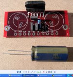
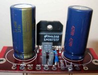
Below is photo of my BrianGT PCB. I'm about ready to install Blackgate caps but when set in place the caps don't match the manual photo. I'm thinking the manual photo is from the first board design and the caps are mounted slightly differently than new pcbs. Could someone knowledgeable answer.
The caps are not marked + or -, although there is a gold strip with a retangular box which May represent a negative sign. It so happens this gold strip is also on shortest connector wire side.
BrianGT, your boards are a dream to assemble. Thanks
Phil
Attachments
Hi,
My NIGC is almost done, but I need to be sure that my power supply board is OK. When I measure the voltage from V+ to +PGND on my power supply board, I get 73V
I was wondering if it's OK
I use a Plitron toroidal transformer (2 x 22V @300VA).
Thanks for your help |
Daniel
My NIGC is almost done, but I need to be sure that my power supply board is OK. When I measure the voltage from V+ to +PGND on my power supply board, I get 73V
I was wondering if it's OK
I use a Plitron toroidal transformer (2 x 22V @300VA).
Thanks for your help |
Daniel
Phil,
That big square on the side IS the minus sign on the cap. I doubt there is text. It's looking good- did you put the NFB resistor on the opposite side?
kanaddict,
You're voltage is too high- 2X what it should be. I'm using that exact same transformer (I think). Did you solder the mains into the transformer in series or parallel? It should be in parallel (white mains wire goes to two transformer leads, black mains wire goes to two transformer leads). I'm guessing Canada uses the same conventions as the States???
BTW, nice handle!
Jason
jtsjf said:It's looking good- did you put the NFB resistor on the opposite side?
Brian was nice enough to build in the NFB resistor to the newer pcb, which I used. I was seriously considering right on the chip but couldn't get my big a** sodering tip close enough to do job without solder crossing to other leads. The overall experience was great, looks very professional.
I can't wait to strip out parts from work spoils, a building automation system. I've got two complete Unity PSUs (trafo ct type multitap, full rectifier, capacitor, main in outlet, switch, primary fuse, secondary fuse, dc out connectors, enclosed chassis). A great find.
Also picked up parts from a 480vac-3phase variable frequency drive (3-6"x12"x4"deep heat sinks, 15-20 load resisters 50w, 12-phase correction capcitors). I plan on slicing the heat sinks on the horizontal band saw here in the shop.
jtsjf said:Phil,
kanaddict,
You're voltage is too high- 2X what it should be. I'm using that exact same transformer (I think). Did you solder the mains into the transformer in series or parallel? It should be in parallel (white mains wire goes to two transformer leads, black mains wire goes to two transformer leads). I'm guessing Canada uses the same conventions as the States???
BTW, nice handle!
Jason
Hi Jason,
Thanks for your reply. I posted my question as a new subject and I got the answer to my question. I measured 73 VAC....I should had measure the VDC ! I'll have to take new measurement.
Thanks!
That's nice that he included the NFB resistor on the board. I have V.1, and after soldering the resistor directly to the chip (also with my big a** soldering iron), I had to clean it up a bit.
Overall, I'm really impressed with Brian's design and layout, and speed. I really appreciate his and many other's efforts. He and his fiancee sent out a ton of orders just before his wedding. Now THAT's devotion....on his wife's part. I'm also real impressed with the shear number of people that have used this kit to build their own amps. That is so cool, it's beyond words.
Kanaddict, if you need a picture of the inside of my amp, let me know. The wiring is pretty straightforward, but sometimes pictures do help. They help me anyway.
Cheers,
Jason
Overall, I'm really impressed with Brian's design and layout, and speed. I really appreciate his and many other's efforts. He and his fiancee sent out a ton of orders just before his wedding. Now THAT's devotion....on his wife's part
. I'm also real impressed with the shear number of people that have used this kit to build their own amps. That is so cool, it's beyond words.Kanaddict, if you need a picture of the inside of my amp, let me know. The wiring is pretty straightforward, but sometimes pictures do help. They help me anyway.
Cheers,
Jason
- Status
- This old topic is closed. If you want to reopen this topic, contact a moderator using the "Report Post" button.
- Home
- Group Buys
- Group order of non-inverted LM3875 pc boards? Anyone interested?