Btw I'm not saying that the TL431 shunt is the perfect match. All that I'm saying is super low z & wide band regs may not be the best match for the Tda. All regs will.always add it's own signature
to the sound regardless. That's the reason why I like passive CLC but due to the close voltage tolerance most dac's it's difficult to get a stable supply voltage. Killed a fair no. of dac along the way but when it was working wow . You should try it sometime that is if you can find a way to stabilise the voltage. lol
Cheers
Hi Ryan, I like your plan, the tl431 being close to the pins will probably make difference than having the best reg on paper on the end of long wires. Thorsten I think said that if you use a large 100-200uF cap after the TL431 reg it will halve the output impeadance to about 0.2 ohm, but this is from memory.
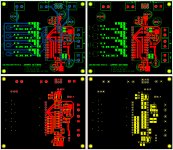
v2 progress update - draft
Thanks for everyones input.
Im trying to keep the design as simple as possible. The shunt circuit using the TL431 is great for this with its very low part count.
I've added space for bigger caps for the 3 power supplies - 5mm pitch; while keeping the 2.5mm pitch in place. The bypass cap in the resistive divider circuit gives you 3 options - 5mm pitch cap, 2.5mm pitch, and I also added a 1206 pad in parallel for the option of a low value film/ceramic for experimental purposes.
I've also added jumpers for mode selection between +5 and -5v inputs - not yet labeled.
Attachments

Hi Audiolapdance
Would be nice to remove the smd by pass caps. Yes I know why it's
technically needed but for me I've never like the sound they impose.
I'm a big fan of BG caps but then I only like the sound of the standard
type, less hi fi sounding.
you can just leave them out if you dont want to use them.
Hi Guys, thanks for the feedback.
Good to see most are happy/satisfied with the direction this project is going. Im happy to add a CCS using lm317/337 - which is what ill be testing and experimenting with anyway. So long as everyone is on the same page, if you wanted to try a different recipe it would be easy enough to bypass these circuits and use your own. Bypass cap for the resistive divider - This cap/caps are not essential for the operation if you choose not to populate, entirely up to you. The 1206 pad in parallel is optional, so feel free to do as you please to suit your tastes. I'll definitely test out various caps in these positions; as it seems to have a big impact on performance in the simulations.
@green77 - Both planes are directly connected at pin 14 (dgnd)
@Audiolapdance - I'm familiar with that circuit, although mine uses lm317/337 as CCS, the 334 is limited by the current it can supply, one advantage is these parts are dirt cheap and are in abundance of supply(LM317/337, TL431) so it seems like a really good option for all diyers, and it *should* live up to expectation or at least perform very well.
@Walter - Me too, if this atten circuit is anything to go by then an improvement in the proximity of the shunt element should be night and day, i'm really looking forward to hearing what the outcome will be. So long as it's not a total failure.
@bkdog - thanks for the info, looks like an interesting design, ill look into it more. On first glance the part count is much higher and it looks like a series reg? Really trying to steer clear of such circuits, keeping the current transient "loop" as close as possible to the TDAs power supply pins seems rather important according to a few experienced Legends. The current steering logic within the 1541 is very sensitive to its outside environment.
In the diy spirit and trying to keep the majority pleased - I've got no problem putting the 317/337 CCS on the pcb.
The positives:
-VERY simple
-Ripple/noise rejection from the source simulates great - it only adds to the overall performance with the shunt element as it seems to operate/reject ripple/noise at a higher frequency, where the shunt circuit seems to improve things down low in the frequency range.
I know there are big limitations within these circuits in their basic form, but if we think of what the TDA is actually asking for then I think It will do more right than wrong.
Hopefully we can come to a consensus. There is just too much at stake.
 - the music
")
Good to see most are happy/satisfied with the direction this project is going. Im happy to add a CCS using lm317/337 - which is what ill be testing and experimenting with anyway. So long as everyone is on the same page, if you wanted to try a different recipe it would be easy enough to bypass these circuits and use your own. Bypass cap for the resistive divider - This cap/caps are not essential for the operation if you choose not to populate, entirely up to you. The 1206 pad in parallel is optional, so feel free to do as you please to suit your tastes. I'll definitely test out various caps in these positions; as it seems to have a big impact on performance in the simulations.
@green77 - Both planes are directly connected at pin 14 (dgnd)
@Audiolapdance - I'm familiar with that circuit, although mine uses lm317/337 as CCS, the 334 is limited by the current it can supply, one advantage is these parts are dirt cheap and are in abundance of supply(LM317/337, TL431) so it seems like a really good option for all diyers, and it *should* live up to expectation or at least perform very well.
@Walter - Me too, if this atten circuit is anything to go by then an improvement in the proximity of the shunt element should be night and day, i'm really looking forward to hearing what the outcome will be. So long as it's not a total failure.
@bkdog - thanks for the info, looks like an interesting design, ill look into it more. On first glance the part count is much higher and it looks like a series reg? Really trying to steer clear of such circuits, keeping the current transient "loop" as close as possible to the TDAs power supply pins seems rather important according to a few experienced Legends. The current steering logic within the 1541 is very sensitive to its outside environment.
In the diy spirit and trying to keep the majority pleased - I've got no problem putting the 317/337 CCS on the pcb.
The positives:
-VERY simple
-Ripple/noise rejection from the source simulates great - it only adds to the overall performance with the shunt element as it seems to operate/reject ripple/noise at a higher frequency, where the shunt circuit seems to improve things down low in the frequency range.
I know there are big limitations within these circuits in their basic form, but if we think of what the TDA is actually asking for then I think It will do more right than wrong.
Hopefully we can come to a consensus. There is just too much at stake.
- the music
Last edited:
Yeah there should be, ill go over all the measurements with a toothpick for the final product. I've got Panasonic 1000uF that should fit fine. BTW 1000uF vs nothing at all in the resistive bypass position simulates 15dB quieter and 500m ohms lower output impedance.
For the power supply caps, ill make sure there is plenty of room for exotic caps.
For the power supply caps, ill make sure there is plenty of room for exotic caps.
- Status
- This old topic is closed. If you want to reopen this topic, contact a moderator using the "Report Post" button.
- Home
- Source & Line
- Digital Line Level
- Group buy/Interest list - TDA1541A Core board.