hi guitar89,
You need to strictly follow what works- you explain you have a 25 0 25 transformer achieving 36 volts, it is then a parallel winding. maths proves this too as 25 divide by .707 is 35.36 volts.
You have explained that you are extending DC to an external case.
over what distance ?
You should have a fuse on the AC primary side, remember to turn off before going anywhere near AC mains, by disconnecting the mains lead.
To confirm this wiring disconnect the mains lead before opening any casework.
You describe the rectifier vaguely, is it a full wave bridge processing a positive polarity ? If so all good so far. how much capacitance are you using after the rectifier ?
My thoughts are that 5600 uf will be approximately what is needed.
What grounding exists at the power supply case ?
i would expect that the negative of the bridge rectifier is grounded to the chassis and the chassis is then connected via a wire to the IEC mains ground connection. i would also expect your capacitor to have its negative terminal with a wire to the chassis. I would expect then that there are 3 wires the first from the negative of the capacitor to the chassis, the second from the bridge rectifier to chassis and the third is a chassis connection enabled to connect the amplifier chassis to the power supply chassis.
If all of this checks out then your power supply is reasonably well wired and should function as a aC derived Dc power supply at 36 volts.
Next I would expect your Dc to arrive at the amplifier case with two wires, the first is 36 volts positive. the second wire will be a ground wire to your amplifier case chassis.from the star ground of the power supply chassis
check this all out and report back.
Last edited:
hm..... you got the point most of it correct (of my situation), but mine is not bridge rectifier. I have some picture/diagram in the another thread (just look at the picture is enough though)
Currently, my PSU's chassis ground (main earth ground connected) is isolated from every other thing, maybe i will test it next week (not available to experiment and build things),does it necessary to have connection from rectifier to chassis ? And the third one i already have, but my amp currently is not enclosed for testing and rectification. (spare a wire already)
If we ground so much to the chassis, won't it be too much (excessive) and will the shocking if i touched the chassis ?
MY reservoir capacitor's capacitance is super over powered....... 23.5MF. I only know its too big after i saw other article about it, but nothing bad comes with better ones ?
Currently, my PSU's chassis ground (main earth ground connected) is isolated from every other thing, maybe i will test it next week (not available to experiment and build things),does it necessary to have connection from rectifier to chassis ? And the third one i already have, but my amp currently is not enclosed for testing and rectification. (spare a wire already)
If we ground so much to the chassis, won't it be too much (excessive) and will the shocking if i touched the chassis ?
Hi
you are showing me a picture of a surface mount component looking like either 0805 or 0603 resistor or capacitor suggesting it can somehow substitute or work as a bridge rectifier.
It can't, you need to study power supplies. a bridge rectifier is 4 diodes arranged to rapidly switch an AC signal, without a rectifier you cannot achieve DC - your power supply by all intents is delivering AC,. to an amplifier designed for DC.
take some time to study power supplies they are a simple but very serious side of electronics.
Cheers / Chris
and 24mf is 24 microfarad a tiny amount of capacitance, and way insufficient to filter AC to form DC with an amplifier at the other end. i believe you are trying to understand electronics, it is a marvellous thing to do, so take your time and understand the basic's. Please take this advice. its great to see you on the forums and we are all here to help.
Last edited:
Electro-Magnetic Compatability ie RF interference, EMI, signal Integrity problems, 50/60Hz hum etc.
As you have pointed out a lot of equipement these days, especially your DVD players etc are double insulated, it makes the engineering easier as you dont have to worry about multiple paths being formed for return currents. Thus you dont have to engineer solutions to any noise problems you may have by having a protective earth connection.
As to safety, it depends how well a product is engineered, but if there are any metal parts exposed, heatsinks etc then you must have a protective earth connection as ALL exposed metal parts should be directly connected to protective earth (PE). I will not build anything with metal that can be touched without that metal part being solidly bonded to the PE and the chassis, metal to metal. I also reguraly have the mains and earth bonding checked, easy for me as we have PAT testing equipement at work that I can borrow.
So my conclusion is PE attached equipement is safer, but involves more engineering for noise problems. Double insulated requires more engineering for the actual physical aspects, ensuring that no internal metal parts that may have mains potential can be reached by any means, not an easy task, when you start adding thermal issues where ventilation etc is required.
I'm showing the transformer configuration is layout (not the first 3 picture, further down)
nono, it is really an DC, try to see this (the second picture)
Thanks for your support, chris. I'm in learning process, but i believe that i'm through with individual component basic (except amplifier ! they work so complicated !)
Marce, what about using double insulation with PE around the touchable metal surface ? (or it will cause massive destruction ?) hm... if using PE style, the most accident only component failure, fuse blown, Circuit breaker trip ? as in Double Insulation more dangerous ?
So in conventional design, they use double insulation to eliminate noise, but we use PE as safety, but hard to reduce noise (even harder to eliminate noise ?).
Seems alot to learn to reduce the noise.... any book recommended for that purpose ?
hm... so what is the following step i need to do now ?
nono, it is really an DC, try to see this (the second picture)
I agreed that bridge is most of the time better, but it required another 2 diode (i don't have the same exact diode here, but i purchase the 40A bridge yesterday, use that ?)
Thanks for your support, chris. I'm in learning process, but i believe that i'm through with individual component basic (except amplifier ! they work so complicated !)
Marce, what about using double insulation with PE around the touchable metal surface ? (or it will cause massive destruction ?) hm... if using PE style, the most accident only component failure, fuse blown, Circuit breaker trip ? as in Double Insulation more dangerous ?
So in conventional design, they use double insulation to eliminate noise, but we use PE as safety, but hard to reduce noise (even harder to eliminate noise ?).
Seems alot to learn to reduce the noise.... any book recommended for that purpose ?
hm... so what is the following step i need to do now ?
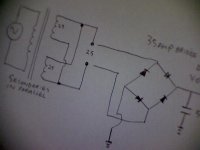
I have looked at the drawing of a capacitor sitting to form a connection to the centretap. this is a very poor implementation and leads to frequency dependency. And it is not DC even after the diodes there will be a substantial AC component. If the secondary windings are the same value in this case 25 0 25 the correct method of wiring a transformer in parallel is in the image. Toroidal transformers are wound fairly precisely. 1N4007 diodes are also way insufficient for any amplifier
So the best part you have in the PSU box is the transformer. the capacitor acting as a swing to somehow create a parallel winding with diodes is I think one of the worst implementations I have ever seen.
No wonder you have noise !!
so before starting disconnect the power cord. send either an image or diagram of markings on the transformer. and lets start there.
Bad farads
uF is a microfarad
mF is a millifarad
MF is a megafarad
MFD is an old designation for microfarad
I think you mean 23.5mF (23500uF) which is a lot of capacitance.
Disregard an earlier suggestion to use "mf".
MY reservoir capacitor's capacitance is super over powered....... 23.5MF. I only know its too big after i saw other article about it, but nothing bad comes with better ones ?
uF is a microfarad
mF is a millifarad
MF is a megafarad
MFD is an old designation for microfarad
I think you mean 23.5mF (23500uF) which is a lot of capacitance.
Disregard an earlier suggestion to use "mf".
ahh... srry, mine was using the "M" instead of "m", typo error X.x Mf should kill anyone if mistaken touch ! (and enormously huge !)uF is a microfarad
mF is a millifarad
MF is a megafarad
MFD is an old designation for microfarad
I think you mean 23.5mF (23500uF) which is a lot of capacitance.
Disregard an earlier suggestion to use "mf".
haiz....... really ? in my mind, this was indeed not good implement (compare to bridge rectifier) and not wrong, but it doesn't make AC after the diodes. (DC per half coil per half wave)
OMG..... i'm going to redo my PSU AGAIN !!! i hate that.... (i just redo it this week, and nicely design in the casing.....)
And the diode isn't 1n4007 i was using (so....... incapable..) Mine was this : ON SEMICONDUCTOR|MUR420G|DIODE, POWER RECTIFIER, UF | element14 Malaysia
I personally felt this is excellent. The bridge rectifier i brought for about six times the price i brought the diode's unit price, but there is no spec, except it is 600V 40A only.... nothing about ultra fast, etc. (so I'm not confident about it) is it an overkill ? or should i buy another low current rating with better speed ?
** I also agree that my transformer is the best thing (high quality) in the PSU **
hm... the marking of the transformer is in the link i gave
well..... if parallel then need to change into "red with Yellow" and "black and orange". with a bridge rectifier.
hm..... now already build the emitter follower and used, no difference in my problem. (what noise does the device attack ?)
I just noticed that the noise happen when the source is plug in. (well.... my amp inhibit its own noise) alot different noise during different situation so i will list out a bit.
(I) power supply of amplifier has problem, going to attempt parallel secondary arrangement (which seems more proper circuit)
(II) Audio Source ? seems not much possible.
**additional** : there is another intermittent noise when any light or AC electrical equipment on/off.
The weird thing is that when i disconnected the computer AC power(use battery), and disconnect the AC plug of main, the intermittent noise will still happen.
I just noticed that the noise happen when the source is plug in. (well.... my amp inhibit its own noise) alot different noise during different situation so i will list out a bit.
So i think there are several possibility, most probably a ground loop problem ?when AC power is off, my amp runs of residual reservoir energy, the noise is at its lowest, which is only hum/hiss. I think is PCB layout problem, so i eliminate the approach to save it (since it is not important ?)
When AC power is on, the source is off, the source is disconnected, the amp noise(buzz) is loud, about at low volume music.
When AC power on, audio source plug in, the amp inhibit another noise(buzz) which is lower frequency than previous. (note that this is an AC connect computer as source)
When situation is same as previous, but the Computer now uses battery, which independent from AC adapter. The buzz disappear and only hiss/hum(same as first condition), which is ideal i think.(for the moment)
Adding safety ground at any point of amplifier in any situation seems doesn't change anything.
(I) power supply of amplifier has problem, going to attempt parallel secondary arrangement (which seems more proper circuit)
(II) Audio Source ? seems not much possible.
**additional** : there is another intermittent noise when any light or AC electrical equipment on/off.
The weird thing is that when i disconnected the computer AC power(use battery), and disconnect the AC plug of main, the intermittent noise will still happen.
- Status
- This old topic is closed. If you want to reopen this topic, contact a moderator using the "Report Post" button.
- Home
- Amplifiers
- Solid State
- Grounding on single rail ? (building aspect)