Brian Beck said:KBK,
Nice unit. Can you post pictures of the internals of the PS chassis too? Your pictures are almost good enough to plot schematics from.

The PS box soon! The phono is easy, I can unhook it while I'm still listening (sat channel, or CD, etc). I'd have to shut the tunes machine down to take pitchers of the PS!

 That would require that the music stop... yuck.
Back to the topic at hand, those big resistors. 2-3 watt??? more like 3-5 watt, is my guess. I need to know, as I'm going to slowly replace them all. Beautiful wire wrap job. Tough to clean up. I love it when an an entire circuit is free air and hard wired together. If you could loose the boards while still retaining some damping and connectivity/support, that would be awesome.
before I forget, speaking on that subject: I asked my sales manager what his some of his best experiences in audio were (he's ben rep, distribution, sales, end user, etc-done it all) He said the Lumi was one..and another, he remembered, as it happened at the same time. A plastic chassis Intergrated, but he didn't remember the name. DNM, I told him. Makes me want to head down that awful road of manufacturing, finally. I got a jones for sharing great gear, I don't like to keep it to myself.
More Excessive Tube Porn
An externally hosted image should be here but it was not working when we last tested it.
The signal box umbillicals connect in the upper left corner, everything flows to that point.
As you can see, I need to clean this box up. I also have a green LED Power swtichy thingie, and a red LED Power switchy thingie , in the bottom right corner. ("The red thingie is moving toward the green thingie"-Galaxy Quest).
I'm curious what they do. I suspect that one is heaters and the other is circuit. The green one doesn't do much at all. The red switch gives a little bit of flicker to the lights in the house, and makes my computer UPS 'click'. There is a Red LED on each signal chassis, wich illuminates along with the Red LED on the PS box. There is a green LED only on the PS box. Normally I would investigate, but it's more challenging to be in ignorance until I buy a schematic from Scott Frankland. I've spent my entire life working on things without ever resorting to schematics or manuals of any kind. I can count the times I've used a tech manual on the fingers of two hands. Either I'm more manly...or retarded. You figure it out.
What works best to clean up the laminations in the trannys, without causing them misery? Emery cloth? My big issue is the possibility of pushing bits of crap into or between the laminations. Eh, emerycloth and then a good paintjob on the end caps. Maybe complete removal of the covers???? Everyone knows you is coolest in your birthday suit. But this is PS trannies, different Frequency bandwith pass/deflect issues. maybe a layer of epoxy on the laminations after a cleaning. maybe a light tremclad rust paint job, but that potential seperation comes back again....
And you can also see that there have been a few things moved about, added, removed, etc. Extra screws in the chassis box....hhhmmm.....
Thanks for posting the PS innards. It looks like one of my DIY rigs with all those trannies and chokes everywhere!
Living in Florida, I’m no stranger to rust. I would suggest orthophosphoric acid to treat residual rust left on smooth surfaces after abrading away the loose rust. But I wouldn’t suggest painting it onto the laminations in the usual manner, since it would soak in between the laminations by capillary action. But I have used orthophosphoric acid on the surface rust of laminations using a rag lightly dampened with the acid. First I gently hand-sanded off the loose rust using fine sandpaper. Then I wiped on a very thin coating of the treatment so that almost no liquid could penetrate between the laminations. Then you can paint the surface with a finish coat.
Living in Florida, I’m no stranger to rust. I would suggest orthophosphoric acid to treat residual rust left on smooth surfaces after abrading away the loose rust. But I wouldn’t suggest painting it onto the laminations in the usual manner, since it would soak in between the laminations by capillary action. But I have used orthophosphoric acid on the surface rust of laminations using a rag lightly dampened with the acid. First I gently hand-sanded off the loose rust using fine sandpaper. Then I wiped on a very thin coating of the treatment so that almost no liquid could penetrate between the laminations. Then you can paint the surface with a finish coat.
I just discoverd a near DC wobble that is obviously signal dependant, in the line section in one channel. This is on the output, obviously. Level sensitive in intensity. More output, more wobble.
Any quick guesses? PS or shorted cap?
This kind of problem in a tube circuit is awful, it's like chasing ghosts.
Any quick guesses? PS or shorted cap?
This kind of problem in a tube circuit is awful, it's like chasing ghosts.
Sure, here it is. Now you owe ME one.
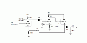
The article was a clone version, so here are some details that may or may not have been original:
The plate resistor of the first stage is made up of four 21k5 1W in series-parallel. The cathode follower/feedback resistor is made up of three 30k1 1W in parallel. The plate resistor for the second stage is made up of two 21k5 in series. And the output cap comprises two 1u0 in parallel, with a 0u1 paralleling them.
Attachments
The Near DC is woofer pumping in bass transients, all level dependant. Higher level, more wobble. One channel only, The right. Yes the right is wobbling. Deservedly so.
Well, I've taken the unit out and subbed my moded counterpoint 3.0. THe counterpoint is now slaying the Magus C I have, which is virtually stock; not an unexpected outcome.
I will be tracing out the line stage circuit, to potentially find the source of the issue.
The most interesting thing to note, is the osc I had when the tip of the RCA on my cotter phono transformer touched the inner of the phono stage RCA, while the phono section was powered up. I think it was right channel only there, as well. What I heard, was the power supply box wobble, in terms of hum and rectification. It corresponed to the exact same osc frequency characteristics of the woofer wobble. ie, sub hz, 0.xHz range.
I miss the Lumi already. Every other preamp I put in there sound is dynamically flat as a rubber board, and I keep having to check and see if the mono switch is on or something.
In over 28 years of screwing around with audio equipment, I've never owned something wicked good.
That Lumi is so 'alive' - there are simply no words for it.
In over 28 years of screwing around with audio equipment, I've never owned something wicked good.
That Lumi is so 'alive' - there are simply no words for it.
Ok. So far, the circuit is almost identical:
First Moore trick (or whomever) uncovered: The heater circuit.
My trick has always been to be absolutely sure that one of, if not the lowest potential ground is right at the heaters, and then utilize extremely low Z caps - right at the pin. Oscons, about 500uf's worth. (I've got a few hunnert spares) Whatever. Problem: If the grounding elsewhere is at fault, then you run into a hum issue.
The solution in this unit: the heater circuit DC supply cap ground point..is elevated above ground, by a 1k resistor. A damped elastic buffer. Float the entire noise, thus eliminating it. That's my off the cuff analysis, when I saw it. You guys will know better, or at least be able to contemplate such with more background in tube circuits than I have.
Just remember, when you go by electron flow ( ye olde: the ground is actually the source..that's why shielding works--otherwise it simply wouldn't do squat) it makes radical and obvious sense.
The ground in this unit travels through about 10 feet-15 feet of cable..yet..it is more (AC hum or otherwise) quiet than -anything- I have ever owned.
Full volume, on phono, with all other possible AC field devices removed from the immediate area, results in simple tube noise, with zero AC hum.
I forgot: Most importantly, the 2 meg resistor in the circuit supplied by Sy, does NOT go to ground. It goes on one end of that 1k resistor. It is that junction between the 2 meg and the 1k, that is the 'ground' point for the heater buffers. The noise, if any, is floated? sneaky sneaky. Oh yes, only the one single 1k resistor for the heater buffer circuit, for both channels and all four tubes.
Make more sense now?
If you think of how that arrangement will affect the sound, you get Arthur Salvatore's comments on the 'characteristic sound' of a Lumi preamp. The buffer cap's quality becomes crutial to the 'sound' of the preamp, in a very direct way, but it also allows the most critical aspects of transient delivery and possible modulation by internal tube issues involving the heaters, to emerge..unscathed. In direct porportion to the buffer cap quality.
well, a couple of options here:
1: I'm an idiot, and you don't want to embarass me by saying it.
2: I'm not an idiot, and you don't want to look like one, by suffering even the potential of being one.
Well, I'm callin' you guys out.
I have my dick in the vise - and I set the garage on fire.
Now where's my hack saw?
Comon guys, it only takes a few seconds to figure it out. Fess up, what do you think? Don't forget to bring the fire extinguisher.
IIRC the 2M resistor goes to a voltage divider across one of the 6.3V filament supplies to provide negative bias to the second voltage amplifier stage. No cathode bias. I think this was about -2V..
Check with Trombone and see whether or not he would be willing to share some of my Lumi mods with you. My docs are long gone..
Check with Trombone and see whether or not he would be willing to share some of my Lumi mods with you. My docs are long gone..
Congrats
Congrats to KBK on EXTREME rarity! I have had a few Lumis over the years, but never saw anything like this one. In fact, NONE of production Lumis had solid state regulation, and all were quite noisy, too noisy for any good low output MC. Yours seems to be closer to later MFA MC Reference in that regard. I currently use an early Lumi A, but am getting tired of it's darkness. Practically impossible to find a sourse or a cartridge that would sound NORMAL with it. Either the rest of system has to be openly bright, or the source has to be bright. Looking for something more open sounding. Good luck! M
Congrats to KBK on EXTREME rarity! I have had a few Lumis over the years, but never saw anything like this one. In fact, NONE of production Lumis had solid state regulation, and all were quite noisy, too noisy for any good low output MC. Yours seems to be closer to later MFA MC Reference in that regard. I currently use an early Lumi A, but am getting tired of it's darkness. Practically impossible to find a sourse or a cartridge that would sound NORMAL with it. Either the rest of system has to be openly bright, or the source has to be bright. Looking for something more open sounding. Good luck! M
- Status
- This old topic is closed. If you want to reopen this topic, contact a moderator using the "Report Post" button.
- Home
- Amplifiers
- Tubes / Valves
- Grounding MFA Luminescence