Venci - forgot to mention :
My clock outputs 2.8, 5.6 and 11.289 so it was easy - apologies.
Anyone with fixed 11.289 clocks will need your design - which on your Alpha 5 looks fantastic - like the use of the ribbon cable and the pc power supply twisted wire and plug - I've used them too - very handy !!
You can beef up your MSB caps to 2.2uf's ( throw away the 4 tants ) and use close tolerance silver mica 250pf across pins 16 and 17 of TDA.
You'll fall off your chair after you've done this
Andrew
Actually the picture shows a reclocking the the whole I2S bus. I didn't like this method. It's actually done by default in Alpha 5+ version of the player. I should update my article with my current reclocking setup. About that small 680pF cap - I'm about to make a DEM reclock and feed the external frequency to the internal oscillator.
Regards,
Venci
Regards,
Venci
As far as I know, pin 4 is not used on TDA1541A in time multiplexed mode.And I'll try the 1541A with separate clock on pin 4.
Well that's what Table 1, page 5 from 1541A datasheet says. I wonder why all the manufacturers had decided to link together pin 2 and pin 4, when pin 4 is actually unused That reminds of the way logic inputs of the IC's are treated. All unused inputs tied to ground or linked together with the used input pin.
That reminds of the way logic inputs of the IC's are treated. All unused inputs tied to ground or linked together with the used input pin.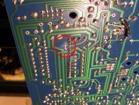
No soldering tonight! Too much reading to do, especially now a clocks in the picture ;o) I couldn't find the 11.289 one earlier but it's just re-appeared, odd. I'll invest in one once I've got a few other things sorted.
I have learned a huge amount already, mostly about how important the placement of components can be to the sound. Until I plugged the op-amps directly into the sockets (i had double socketed them to make it easier to swap), it seems the extra socket really upsets them (I wouldn't have believed it could matter that much) but the magics back! - Is this a result of 'long' leads to the opamps or just too many crumby connections I wonder.
So, the next job is to get the PSU sorted for the 7220 (the whole things sitting in a box of to one side at the moment, a couple of wires looped in and under the chip.) Then I/V, probably just a simple, separate opamp board with a dedicated psu for now while I do my homework. Then....hmmm....clock perhaps, the 7220B.....better PSU.....
All this clock talk though......maybe I just hit the 'buy it now' button......
I can't stress enough the difference removing those extra sockets has made, my wife came in last night and said 'ooh that sounds nice', and all I could think was 'hmm,to me it's a bit muddled and flat', now with the extra sockets out I'm happy again. Oh dear, is this the bit where the obsession kicks in? ;o)
I can't stress enough the difference removing those extra sockets has made, my wife came in last night and said 'ooh that sounds nice', and all I could think was 'hmm,to me it's a bit muddled and flat', now with the extra sockets out I'm happy again. Oh dear, is this the bit where the obsession kicks in? ;o)
Yes !
Also very soon your wife will not be remotely interested and will become increasingly agitated
 , fed up with the smell of solder, the mess you make and your lack of sensible communication
 .
.This is normal - tell her tonight
Ahh so you have the pin 4 disconnected. I'll try this. I still wonder why commercial designers tie these together.
Regards,
Venci
To save money maybe ?
They cut corners to maximise their return on investment - why not - what did we know ?
That's why our machines are filled with the crap that we must change and modify to make them work properly and...it's why we are all here !!
Naim Audio CD Players as an example - get the lid off and see the cheap crystal inside and then remind yourself how much their players cost - it's a joke
We are the idiots - not the engineers who do as they are told - we paid their wages for years and some fools still do.
' No user service able parts inside ' remember that label on the back ?
That translates - ' please don't see the mess we made inside or... tell anyone if you do '
Profit first - music second
Andrew
If only price was always 'cost+margin', rather than 'what we think the market will stand'. Mind you - I'd be out of a job, the cost+margin calculation is difficult to apply in the software industry.
No tweaks this weekend, family time away - I can feel my frustration already ;o) Still, I hope to get the op-amp I/V in on Sunday, they will be directly soldered (one with opa's, one with the originals) with a dedicated PSU. If I get time I might mount the whole thing on a board for now as it's going to get really tight on space otherwise.
No tweaks this weekend, family time away - I can feel my frustration already ;o) Still, I hope to get the op-amp I/V in on Sunday, they will be directly soldered (one with opa's, one with the originals) with a dedicated PSU. If I get time I might mount the whole thing on a board for now as it's going to get really tight on space otherwise.
No more mods yet - just prepping the board layout for the i/v and PSU. I was going to knock something up on Sunday with strip board but my experience so far has lead me to spend a bit more time on the preparation and build quality, so a 'proper' board is in the works.
Anyway, on the subject of mounting things in sockets, do the same principles apply to the TDA1541 and the SAA7220? I've got the DAC in a socket and was planning to do the same with the SAA but am I sacrificing quality for convenience?
Cheers
Anyway, on the subject of mounting things in sockets, do the same principles apply to the TDA1541 and the SAA7220? I've got the DAC in a socket and was planning to do the same with the SAA but am I sacrificing quality for convenience?
Cheers
I have the SAA7220P/A in at the moment, with a B arriving shortly, hence the socket. I don't know how much soldering/resoldering the board will take so I may just solder the /B straight in and hope!
At present the I/V stage will be nothing more than a replica of the one described in the datasheet, I'm building two though, one with the opa134's and one with originals. They will be modular, with a dedicated +/- 15v psu. The idea is that once I've lifted the DAC outputs I should be able to play around with the output and PSU without having to dismantle the entire thing.
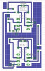
I've attached a screenshot of the board from Eagle, ignore the annotation, I like to draw freehand! There is also some fill on there to save on etch ;o) This is the first sketch, so go easy on me! I've tried to keep the decoupling close but I've had to use jumpers as I haven't tried double sided yet.
Basically, over on the upper left are some pads and these will be, from the top, +15v, -15v, Gnd, Left & right in. On the right are three more, Left, Gnd & Right outputs. Any other pads are for jumpers. The pads will have to grow to fit terminal blocks but I can't find them at the moment and I can't remember the spacing!
The PSU will be a fairly standard affair using 78** and 79** for now as they're all I have to hand, at least the op-amps will have their own power.
I'm not expecting miracles from this but it'll keep me busy for a while!
At present the I/V stage will be nothing more than a replica of the one described in the datasheet, I'm building two though, one with the opa134's and one with originals. They will be modular, with a dedicated +/- 15v psu. The idea is that once I've lifted the DAC outputs I should be able to play around with the output and PSU without having to dismantle the entire thing.
I've attached a screenshot of the board from Eagle, ignore the annotation, I like to draw freehand! There is also some fill on there to save on etch ;o) This is the first sketch, so go easy on me! I've tried to keep the decoupling close but I've had to use jumpers as I haven't tried double sided yet.
Basically, over on the upper left are some pads and these will be, from the top, +15v, -15v, Gnd, Left & right in. On the right are three more, Left, Gnd & Right outputs. Any other pads are for jumpers. The pads will have to grow to fit terminal blocks but I can't find them at the moment and I can't remember the spacing!
The PSU will be a fairly standard affair using 78** and 79** for now as they're all I have to hand, at least the op-amps will have their own power.
I'm not expecting miracles from this but it'll keep me busy for a while!
Attachments
- Status
- This old topic is closed. If you want to reopen this topic, contact a moderator using the "Report Post" button.
- Home
- Source & Line
- Digital Source
- Grounding dedicated PSU for SAA7220