chassis ground of most devices is connected to live through capacitors. The resulting currents are called residual or leakage currents and range from 0,1-0,5mA in case of safe insulated equipment or up to 3mA for equipment connected to protective earth.jneutron said:
You're going to have to explain that statement a little better.
These currents find their way through the net between devices and between devices and the mains outlets according to Ohms law and Kirchhoffs rules.
So we are talking about of almost mAs of 50/60Hz current circulating the grounds of your home stereos.
This is way more than the wiring can pickup through magnetic coupling.
jneutron said:
My experience certainly is not consistent with that statement. I have used the techniques many times with success.
so you are a lucky man.
")
I wish I could resolve hum problems that easy.
Now add to the problem the obsolete 'classical zero' wiring found sometimes in elder buildings.
This wiring method carries only live and neutral to the outlet. PE is created by local connecting the PE pins to the incoming neutral at the outlet.
Now the potential on PE floats a little bit with the voltage drop on the neutral wire. Not a safety problem, but no good for audio.

And of course some people want to connect their stereo to somewhere elses grounded antennas or cable tv networks.

regards
Don'tya just love the wondrous things about the house?Juergen Knoop said:chassis ground of most devices is connected to live through capacitors. The resuliting currents are called residual or leakage currents and range from 0,1-0,5mA in case of safe insulated equipment or up to 3mA for equipment connected to protective earth.
These currents find their way through the net between devices and between devices and the mains outlets according to Ohms law and Kirchhoffs rules.
So we are talking about of almost mAs of 50/60Hz current circulating the grounds of your home stereo.
Actually, when you say "most devices", you mean double insulated ones.
And why should these devices have diplomatic immunity from consideration?
As I have stated, I am first dealing with magnetic induction problems.
Juergen Knoop said:This is way more than the wiring can pickup through magnetic coupling.
Actually, no.
It all comes down to the trapped flux and the loop resistance.
Juergen Knoop said:so you are a lucky man.
I wish I could resolve hum problems that easy.
Actually, I am not a "lucky" man.
What I build and use has the standard e-field shielding, just like everybody else. When I use standard "rules of thumb" like you are speaking of, typically the results are great. Your rules are very easy to use, and everybody including myself, are lazy people who will do the least to get the job done..
When the rules of thumb you speak of do not work, I apply my rules. So far, my rules have fixed everything your rules fail to fix...your "rules" do not even understand nor consider my analysis. But they are still good rules when they work.
You have no idea how many "audio engineers" claim that what I speak of will not work, cannot work... but yet, no matter how loud they protest, my fixes worked.
Such is life. It would appear that my work, and some of my play, are outside your experience...no problem..
If you find hum problems that you cannot solve with your methods, perhaps you should consider other methods...like mine perhaps? They say that insanity is repeating the same thing over and over, and expecting different results..
Do not divert the issue..I have started with induction, discuss that.Juergen Knoop said:Now add to the problem the obsolete 'classical zero' ......
I am aware of the "classic"..
Juergen Knoop said:And of course some people want to connect their stereo to somewhere elses grounded antennas or cable tv networks.
regards
I do not know what the power delivery system is where you are, I know the one bushing transformer system here. And as I stated, it is an issue to address at another time...for now, it is magnetic induction induced ground loop currents..
If you do not wish to discuss magnetic induction and ground loop currents, the topic of my thread, then simply do not post..
Cheers, John
I'm sorry!jneutron said:
If you do not wish to discuss magnetic induction and ground loop currents, the topic of my thread, then simply do not post..
But I was referring to ground loop currrents!

I jumped in because of your optimistic promise, which I don't share, because the currents are due to another reason than induction.
yes, please give us numbers!for now, it is magnetic induction induced ground loop currents..
regards
Use an high permeability ferrite core so that you get close to 100mH magnetizing inductance, and the inverting op-amp trick to simulate a short circuit load. You will be able to get a clean signal with flat frequency response down to 40Hz or so (or even lower). A coupling capacitor is required, and some series resistance to damp the resulting RLC tank and avoid peaking before roll-off.
You are currently seeing too much high frequency hash because output increases at 20dB/oct due to the low inductance/permeability. It's probably rolling off below 10Khz or so. It's not a good idea to rely on magnetizing inductance as a load, there are too many uncontrolled variables and low frequency sensitivity is very poor.
You are currently seeing too much high frequency hash because output increases at 20dB/oct due to the low inductance/permeability. It's probably rolling off below 10Khz or so. It's not a good idea to rely on magnetizing inductance as a load, there are too many uncontrolled variables and low frequency sensitivity is very poor.
Juergen Knoop said:
I'm sorry!
But I was referring to ground loop currrents!
No, actually, you are not. You are talking about ground leakage currents.
And do not apologize...your discussion, your alternate take and ideas, is the entire reason for forums...I welcome your input..
Perhaps a clear set of definitions is in order to alleviate confusion.
1. Ground leakage currents are the result of an impedance between a potential above ground to ground. They will attempt to return to the source (the service panel) via whatever means possible, either the line cord neutral, another box's ground cord/ neutral via the IC, or through us (gulp). As you point out, 2 prong double insulated widgits can leak by design. And they can cause hum.
2. Ground loop currents are the result of closing a conductive path around some time varying magnetic field such that a voltage is introduced in that path via faraday's law of induction. Break the conductive path, the current immediately stops. What will be left behind is potentials..ones that can be easily measured from ground to ground.
It would appear that you seem inclined to believe that ground leakage is fully or mainly responsible for all hum problems, and that induction does not. Your premise is good for many applications, and I use it where it works.
It is of no concern to me whether or not you believe me, that changes not the facts.. You need to do a little research on pin 1 problems, look up Bob Whitlock of Jensen Transformer fame, and read about what he is talking about.. There are real problems out there, especially in the pro world, where balanced differential trans/rcvrs do not solve the hum problem because it is current induced on the shields, currents that run through the line cord ground. Building wiring is very bad for this, because of the size of the loop and the fact that the power currents are within 2 to 3 mm (hey, your on the other side of the pond) of the safety ground. Bundling of these AC wires breaks the mirror symmetry of the (romex), and that is a huge inducement for ground loop currents. They await only the poor victims (us) to complete the conductive paths.
Juergen Knoop said:I jumped in because of your optimistic promise, which I don't share, because the currents are due to another reason than induction.
Your currents...your examples.. which I concur do happen.
But yours are but a subset of the reasons. I give another.
And I provided a solution which is elegant by simplicity, and when hum is caused by induction via that path, it works very well. I was suprised how well when I did it using a 100 foot extension and unbalanced line level..
That I most certainly will do.Juergen Knoop said:yes, please give us numbers!
regards
Eva said:Use an high permeability ferrite core so that you get close to 100mH magnetizing inductance, and the inverting op-amp trick to simulate a short circuit load. You will be able to get a clean signal with flat frequency response down to 40Hz or so (or even lower). A coupling capacitor is required, and some series resistance to damp the resulting RLC tank and avoid peaking before roll-off.
Eva...I gots what I gots..87 turns for .5 mH, your talking 200 times the inductance with my core, that's 14 times 87, that's a thousand turns.....yuk . What makes you think I can count that high??
I see the hash because the derivative of sin(xt) is -x cos(xt)...Eva said:You are currently seeing too much high frequency hash because output increases at 20dB/oct due to the low inductance/permeability.
Which is the magnet world way of saying.....20 dB/oct...
Eva said:It's probably rolling off below 10Khz or so. It's not a good idea to rely on magnetizing inductance as a load, there are too many uncontrolled variables and low frequency sensitivity is very poor.
I haven't had the chance to run a full range fro 20hz to roughly 4Khz (higher scares me with the Kepco, I haven't found the spec on it's bandwidth yet..), but when I do, I'll post it.
Remember, this is not yet about mass production, it's just R + D. Whether I build something that is fully practical is not the immediate goal. Level of effect is.
But I still hear ya...
Cheers, John
megajocke said:Those yellow toroids... .micrometals #26
Excellent. Just looked up micrometals, it measures physically exactly like a T90-26.
I ran the numbers...they spec the core as 70 nH/N squared..
500,000/(87*87)= 66.05
Rather close, I'd say.
Looks like I have a permeability of about 70 to 75...
Cheers, John
jneutron said:
And I provided a solution which is elegant by simplicity, and when hum is caused by induction via that path, it works very well. I was suprised how well when I did it using a 100 foot extension and unbalanced line level..
[...]
Eva...I gots what I gots..87 turns for .5 mH, your talking 200 times the inductance with my core, that's 14 times 87, that's a thousand turns.....yuk . What makes you think I can count that high??
I've also sucessfully used the "C" method you showed in your first post when connecting PA sound. The cables we had from mixing desk to power amplifiers were unbalanced. Usually it started out with someone else connecting the stuff up and taking power to the power amplifiers at the stage and power to the mixer from another outlet near the mixing position... One time this went unnoticed until they started up the light dimmers

Taking an extension cord from the stage to the mixing desk solved the problem each time!
On the inductor matter, I think Eva is suggesting you use another core - one with much higher permeability. If you like to reuse stuff from power supplies you could use the core from the common mode filter on the input or the power transformer of the supply if ungapped. Permeability of these materials is a lot higher!
The line filters are usually 3E25 material or similar.
megajocke said:I've also sucessfully used the "C" method you showed..
Here the dimmers, the HVAC both gave problems, and a coupla cycling 5 megawatt power supplies..I swear the building girders warm up from the eddies..
megajocke said:On the inductor matter, I think Eva is suggesting you use another core - one with much higher permeability. If you like to reuse stuff from power supplies you could use the core from the common mode filter on the input or the power transformer of the supply if ungapped. Permeability of these materials is a lot higher!
The line filters are usually 3E25 material or similar.
Sigh...I have the common mode core on my desk..it's .660 OD, .385 ID, and .310 thick. I'd hate to cut it to put it over an RCA though.
I might still be able to use the existing, but it will no doubt require massaging the data that it provides.
I'd hate to actually have to do some calculations...there's no romance in that!!! Calculations are for geeks..DIY is all about the meshing of McGyver and Tim Allen...no smoke, no fun..no excitement..
I've also been considering the use of 8 coil packs arranged around the ic in a pseudo-toroidal fashion, and doing it without a core at all. The most difficult thing will be centering the wire under test.. But at least I can bug a friend of mine to use his fly fishing turns counter thingy to wind 8 random packed coils on some plastic bobbins..that way I don't have to learn how to count...
Next I'm gonna measure the plitron inductance over freq.., I may just keep it ungapped, it's ID is 1.25 inches, so an IEC fits.
Cheers, John
ps..for the summer app, I just made my own snake from the stage. it carried the stereo feed to the stage in one mike cable, I was not too concerned with channel seperation at 10Khz...and it had one microphone cable to the mixing rack.
Attachments
I don't know whether this is related with the subject or not. But I once opened up a DVD player because I was wondering why it had a certain noise spectrum, took the power supply out accidentally disconnecting a metal tab between the power ground and the chassis. After putting it back together, the noise spectrum increased, and now I have to listen to more noise until I have time to figure it out.
50/60 Hz noise is a bad one when looking at the noise spectrum of an amplifier. It is commonly the highest in level, and if you connect a shielded probe to the input and position it open in the air, the 50/60Hz level normally increases.
50/60 Hz noise is a bad one when looking at the noise spectrum of an amplifier. It is commonly the highest in level, and if you connect a shielded probe to the input and position it open in the air, the 50/60Hz level normally increases.
soongsc said:I don't know whether this is related with the subject or not. But I once opened up a DVD player because I was wondering why it had a certain noise spectrum, took the power supply out accidentally disconnecting a metal tab between the power ground and the chassis. After putting it back together, the noise spectrum increased, and now I have to listen to more noise until I have time to figure it out.
I figured it out already...put the tab back!!
There...I'll bill ya later..
soongsc said:50/60 Hz noise is a bad one when looking at the noise spectrum of an amplifier. It is commonly the highest in level, and if you connect a shielded probe to the input and position it open in the air, the 50/60Hz level normally increases.
In the home enviro, there's e-field, and there's m field.
E field is a capacitance coupled thing. We were all taught in school about shielding, and capacitance shielding was the nature of the beast.
M field is NOT a capacitance thing, it is a loop thing. It's there that the schooling we received is inadequate. That's why I like it so much...well, that and I do magnets for a living...
Cheers, John
The tab is back, just at a slightly different location probably differs by a few mm.jneutron said:
I figured it out already...put the tab back!!
There...I'll bill ya later..
but that doesn't solve the increased noise problem. Looks like white noise.Is it possible to determine if noise is caused by E field or M field?
In the home enviro, there's e-field, and there's m field.
E field is a capacitance coupled thing. We were all taught in school about shielding, and capacitance shielding was the nature of the beast.
M field is NOT a capacitance thing, it is a loop thing. It's there that the schooling we received is inadequate. That's why I like it so much...well, that and I do magnets for a living...
Cheers, John
In the pro world (where balanced signals on XLR3 are the norm), hum is normally due to poor design. If you do it right, then hundred meter runs past fractional the fractional MW pulse switching systems that is dimmer land is routine and just works.
The trick is that the screen must be connected directly to the case at both ends (and not with a mile of internal trace to radiate first), and the internal single ended signal reference must be connected to case ground at ONE point. The internal signal reference does not get exported from the box at any point.
Common mode chokes are often built into the input stage to help with CMRR at high frequencies, and it is arguably good practice to follow the input stage with an active LPF at 70K or so to remove out of band hash.
Currents (even quite a lot of current) circulating around this loop has no effect on the internal circuitry and has only minimal effect on the pickup by the cables.
Tony Waldron at Cadac has done quite a lot of work on this, some of which is available here:
http://www.compliance-club.com/archive/old_archive/020514.htm
http://www.fragrantsword.com/twaudio/audio/QualitybyDesign.html
And for overall system architecture, see here:
http://www.compliance-club.com/archive/old_archive/020918.htm
http://www.compliance-club.com/archive/old_archive/021122.htm
Now, obviously this applies to pro audio kit that has the advantage of running balanced.
For unbalanced stuff, minimizing loop areas and possibly using a differential input stage may help.
Just my take on it.
Regards, Dan.
dmills said:In the pro world (where balanced signals on XLR3 are the norm), hum is normally due to poor design. If you do it right, then hundred meter runs past fractional the fractional MW pulse switching systems that is dimmer land is routine and just works.
The trick is that the screen must be connected directly to the case at both ends (and not with a mile of internal trace to radiate first), and the internal single ended signal reference must be connected to case ground at ONE point. The internal signal reference does not get exported from the box at any point.
I certainly concur on design as an issue. Grounding directly to the case certainly does good, as long as the case current path doesn't go by sensitive stuff willy nilly, Bill Whitlocks test looks for that well..
dmills said:Now, obviously this applies to pro audio kit that has the advantage of running balanced.
For unbalanced stuff, minimizing loop areas and possibly using a differential input stage may help.
Agreed, specially the loop area..(well, obviously I would agree...)...differential would be great if the source were also, making pseudo-diff I see as more of a problem when you use two unbalanced ins with a hard ground, as what exactly would the diff stages be rejecting....especially when some of the return current isn't through the screen..but through the safety ground..
Cheers, John
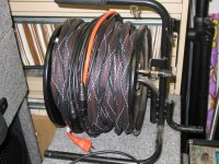
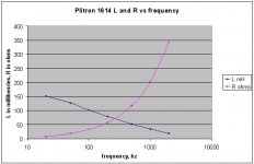
Here's the plitron info.
It is a #1614, 225 va, 50 hz, there's also the number 067014011 on it, whatever that means..
Ran it from 20hz to 2Khz..boy, don't know what the core is, but it hits the skids awfully fast.. I think it may have been designed to also filter stuff out..
Here's the plot. I used one of the secondary winds, and was also suprised at how fast resistance climbed. I'll have to unwrap one to get the wire details, guage and turns..
Cheers, John
ps..don't forget, R increase is certainly not consistent with the skin effect exponential approximation equation. One must always consider the flux environment the wire is in, as the core proximity will affect the wire's current distribution profile..
Attachments
jneutron said:I certainly concur on design as an issue. Grounding directly to the case certainly does good, as long as the case current path doesn't go by sensitive stuff willy nilly, Bill Whitlocks test looks for that well..
Actually, experience is that as long as the internal layout is sane (which it needs to be to pass EMC tests) current flowing between ground connections via a continuous metallic case has remarkably little potential to produce induced currents on wiring within that case.
This effectively just treats the entire contents of the case as your wrapping the earth connection around the chips. In the ideal case (a superconducting cavity) there can be loads of current flowing in the case, but zero current induced in a loop of wire inside the case).
Now obviously most of us don't have superconducting cases, but the idea is the same and it does work remarkably well. To do it right does tend to require EMC gaskets and suitable surface treatment (and at least one screw every inch along screwed joins).
A few amps of loop current is jut not that big a deal.
Regards, Dan.
dmills said:Actually, experience is that as long as the internal layout is sane (which it needs to be to pass EMC tests) current flowing between ground connections via a continuous metallic case has remarkably little potential to produce induced currents on wiring within that case.
It certainly does raise the reluctance path, so provides a lower inductance and magnetic field component. It is important to spread the current as fast as possible to reduce the current density.
I've seen insane layouts that meet emc but were garbage. You can stuff some crazy things into a box if you have no holes, and use capacitive feedthroughs. But that isn't good engineering practice.
You've never had a current modulate a surface permeability? Tom Van Doren spoke a tad about that..
dmills said:This effectively just treats the entire contents of the case as your wrapping the earth connection around the chips. In the ideal case (a superconducting cavity) there can be loads of current flowing in the case, but zero current induced in a loop of wire inside the case).
Actually, that is not quite correct.
The only case which has current flowing but no internal magnetic field within a superconductor or normal conductor is the cylinder. If you examine my moniker, you see the magnetic field density of a coax constructed with two cylinders. Within the center one, there is zero field, between the two, there is only the 1/r of the inner, and outside the outer, there is complete cancellation.
Once you diverge from the cylinder, even a superconducting box supports magnetic field internally as a result of wall currents. It won't let any pass through of course (until the critical current density of the superconductor has been exceeded, typically a kiloamp or so per square mm for niobium titanium).
But I admit, it is an interesting problem..
Some of us do...dmills said:Now obviously most of us don't have superconducting cases,
would you believe that one of the problems is when it goes superconducting it will freeze and keep the magnetization it saw just before transition. Ya gotsta keep a super cavity in zero field as you cool it through transition.You would not believe how accurately skin effect and normal conductors describe as compared to current density distribution within superconductors...every single solitary skin effect article I have read (that was written accurately) mimics greatly what supers do. Dr Sullivan's IEEE stuff is classic and great..dmills said:but the idea is the same and it does work remarkably well.
dmills said:To do it right does tend to require EMC gaskets and suitable surface treatment (and at least one screw every inch along screwed joins).
A few amps of loop current is jut not that big a deal.
Regards, Dan.
You do seem to be worried more about what the box does to the environment than what the box does to the box..you sound like one of dem stinkin emc guys, the sworn enemy of design and production...
A few amps of loop current is not a big deal if it is dealt with properly, which you've gone to length at describing.
This thread is about describing it, what it does, how it works, how to measure, how to counter.
PS....ahhh, a very very important point you have raised!!! which I forgot to mention..
The techniques which are used for EMC compatability are exactly the same techniques which are used for control of current path.. The problem is, these techniques have not been considered heavily in the design of audio equipment, but they should..
Cheers, John
Another word on EMC compatibility and design.
It is typically used to prevent stuff from going through the walls of the device...either in, or out.
For high end audio, it is a case of doing that at low frequencies and low impedances, typically below 377 ohms...so it means magnetic issues are more important than a faraday box, or gasketed seals for e/m waves..
I just had a thought on my loop current drive structure. I'm going to wire the plitron primaries in series with an outlet and perhaps a dimmer/light bulb, or a rectifier/cap/resistor.
Then, run the amp cord through the toriod as a 1 turn secondary. The series element is to prevent burning the wire under test, as it would be a shorted turn to the toroid. And a dimmer to provide hf hash, a rectifier to provide half haversines.
I gotta work on making it NRTL compliant however, as I can't take it to work otherwise. Rules, ya know..
I'm also gonna borrow a clamp on probe, an active one that is 10 volts per amp IIRC, and a bandwidth over a meg.
Hey, if anybody else wants to duplicate this effort, please do. I'm feelin kinda lonely out here.
Cheers, John
jneutron said:Another word on EMC compatibility and design.
<nip>
Hey, if anybody else wants to duplicate this effort, please do. I'm feelin kinda lonely out here.
Cheers, John
Well, despite SY's saying that the tube guys would benefit, most of the "heavy hitters" don't probably come and read anything in this section...
Thus the lack of activity... it would be nice for those with some chops in this area to get involved!!
I hearby tender the motion for moving this thread to a more oft read forum section.
Perhaps dump a link into the Tube section for those interested to follow over? Putting this one into Solid State...
- Status
- This old topic is closed. If you want to reopen this topic, contact a moderator using the "Report Post" button.
- Home
- Design & Build
- Parts
- Ground loops and containment