I have exactly the same problem with my aleph x. single trafo and single PS filter caps. when only one rca conected no hum. as soon as I conect second -hum.. I take zero potential to pcb gnd. spekers out is from dedicated SP+ and SP- from krisitijans pcb.
rca + fron input + on pcb and rca- from gnd from pcb. I tried to conect 7ohm resistor to chasis from ps zero potential but nothing changes..
rca + fron input + on pcb and rca- from gnd from pcb. I tried to conect 7ohm resistor to chasis from ps zero potential but nothing changes..
Hi Cortez
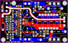
Ref. to your nice picture.
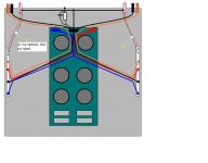
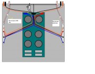
The mother ground line arranged on the amp PCB is colecting her all baby branches on it (like a fish bone), and it is running out of the PCB to the star ground on the PSU board as you indicated with the thicker black color line. Meanwhile, the input RCA gound line is also running directly into the star ground. Therefore, the additional input RCA ground line to the amp PCB is considered redundant.
Anyway, Jleaman seems to be not intersted in our suggestion . . .
Regards
Ref. to your nice picture.
The mother ground line arranged on the amp PCB is colecting her all baby branches on it (like a fish bone), and it is running out of the PCB to the star ground on the PSU board as you indicated with the thicker black color line. Meanwhile, the input RCA gound line is also running directly into the star ground. Therefore, the additional input RCA ground line to the amp PCB is considered redundant.
Anyway, Jleaman seems to be not intersted in our suggestion . . .
Regards
Hello Fellows
It is my amp that Jleaman is working on. He is very interested in your ideas. He is just a bit busy right now and has not had a chance to respond. His time is zone is pacific so he is just getting up right now.
Try to be a little more patient, he will respond once he gets a chance.
It is my amp that Jleaman is working on. He is very interested in your ideas. He is just a bit busy right now and has not had a chance to respond. His time is zone is pacific so he is just getting up right now.
Try to be a little more patient, he will respond once he gets a chance.
Banned
Joined 2002
Hi Jason
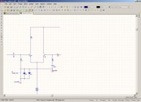
I could be wrong as I have not seen the schematic but looking at the power amp PCB there seems to be a wiring error.
you need to isolate the feedback ground and input grounding resistor
from power ground and connect the feedback and input ground nodes back to power ground via a 10 Ohm 1 Watt resistor and
place back to back 1 amp diodes across the 10 Ohm resistor.
This will isolate the signal ground from power ground and prevent
and ground loop currents from happening, The diodes are there to prevent the 10 ohm resistor from going open circuit in an overload condition in the output stage, such as a short circuit.
I hope this helps
Banned
Joined 2002
The Saint said:Hi Jason
I could be wrong as I have not seen the schematic but looking at the power amp PCB there seems to be a wiring error.
you need to isolate the feedback ground and input grounding resistor
from power ground and connect the feedback and input ground nodes back to power ground via a 10 Ohm 1 Watt resistor and
place back to back 1 amp diodes across the 10 Ohm resistor.
This will isolate the signal ground from power ground and prevent
and ground loop currents from happening, The diodes are there to prevent the 10 ohm resistor from going open circuit in an overload condition in the output stage, such as a short circuit.
I hope this helps
SWEET
 some aussie help
 Would you be able to draw up a brief discription of your idea ? Just so i can look at it ? This is a friends amp and i have already cooked toast with it for him and he has too..
HAH Right scott WINK WINK !!
Banned
Joined 2002
The Saint said:Hi Jason
This should help
Can you possible zoom in a little it's really blurry
Banned
Joined 2002
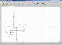
The Saint said:try this one
What you should do is take a hi rez screen shot then just cut out the circuit part in ms-paint or photo shop and keep it at the hi rez then just email it to me
Banned
Joined 2002
Ok i connected it just like this. I dont know the value of the components you drew on the ac ground but they don't mae a difference in any case on this amp. remove the earth ground and it is still there. next suggestion is anthonys BUT im unclear how to connect it with this setup as it is not mine i don't want to be killing more amp's
here is a closer Pic
here is a closer Pic
An externally hosted image should be here but it was not working when we last tested it.
Attachments
Hi Jason
The Modification that needs to be done have to be done
on the amplifier module PCB not anywhere else.
Send me a schematic of this amplifier and I will draw up a schematic for you, so you can see what changes have to be done to the amp module.
It will fix this problem, this would be the most common problem in any power amplifier and it is so easily fixed.
Banned
Joined 2002
The Saint said:Hi Jason
The Modification that needs to be done have to be done
on the amplifier module PCB not anywhere else.
Send me a schematic of this amplifier and I will draw up a schematic for you, so you can see what changes have to be done to the amp module.
It will fix this problem, this would be the most common problem in any power amplifier and it is so easily fixed.
Here you go bud..!
http://www.diyamps.com/aleph/docs/miniAleph-sch.pdf
Ok Jason
I have modified the Bmp of your PCB overlay
and I have had a look at the schematic you sent me.
The schematic is mostly correct, but as I suspected there is a
small error on the PCB layout.
You need to cut the SG track where shown on the overlay
and run a link wire from SG to the node of R0 and Z4
This will connect the Signal ground as shown on the schematic
and correctly isolate signal ground from power ground.
also increase the value of R0 to 10 Ohms.
Thats it!
Attachments
- Status
- This old topic is closed. If you want to reopen this topic, contact a moderator using the "Report Post" button.
- Home
- Amplifiers
- Pass Labs
- Ground Loop problem