I have the same problem on my 6SN7 Aikido...still chasing down how to solve it.
It is definitely influenced by too high of a Q for my PSU stage with the choke...the LF response of the LC filter has a very large peak around the 5Hz range, which causes any oscillations there to be magnified. (Problem is, when I increase the resistance to damp the Q, it kills the sound)
In addition, when I simulate with PSUD, my PSU has an output impedance of close to 1500 ohms. That high impedance may be coupling my driver stage to my output stage, causing some feedback between the two stages.
I am in the process of rebuilding my PSU, which will lower it to about 500 ohms effective impedance. I also intend to experiment with some VR tubes, which should lower it to about 50 ohms.
I also intend to investigate one set of grid stopper resistors (I used a metal film), and a potentially suspect voltage divider which has a carbon comp feeding into a carbon film (perhaps the uneven loading is pushing the very low frequency signal artifacts into the circuit?)
I wish I had a scope....I really need to buy one and figure out how to use it.
Have you lifted the feedback circuit at the OPT to see if (1) the volume increases or (2) the cone motion symptom stops? If the volume actually decreases on lifting the fb loop out, try reversing the primaries on the OPT. You may have a positive feedback situation that is marginally stable until the pre-amp throws it into instability at low frequencies.
Jeff Yourison said:Have you lifted the feedback circuit at the OPT to see if (1) the volume increases or (2) the cone motion symptom stops? If the volume actually decreases on lifting the fb loop out, try reversing the primaries on the OPT. You may have a positive feedback situation that is marginally stable until the pre-amp throws it into instability at low frequencies.
It is a preamp. No OPT.
The B+ connects straight to the plate of the top triode in the driver stage and the output stage. A highish PSU output impedance can apparently couple these two stages together .
Hi,
Been busy of late at work so not made alot of progress with the ongoing problem of flapping speaker cones.
However, following advice from yagas
I changed the coupling caps on the pre-amp from 0.47uf to 0.1uf (found some Wima MKP's at the bottom of my spares box)") This has greatly improved the situation - cones are pretty much static now except for the occasional fluctuation.
This has greatly improved the situation - cones are pretty much static now except for the occasional fluctuation.
But I still feel I should go ahead with regulating the B+ supply as suggested by SY & others. I've had a quick glance at a few old threads regarding the Maida regulator but I'm not really understanding the best way to do this - I'm a total newbie remember.
Based on the measurements made on my pre-amp I have 275V for B+ (after 2nd 50uF cap) and 155V on the 5687 anode. I guess I need to regulate 275V with as little loss of voltage as possible to maintain a similar operating point for the valve. Anybody able to suggest suitable resistor values (R5 & R7) for the Maida regulator. I reckon the 5687 is drawing only 10-11mA. ( I have some TIP50 & LM317 available so Maida seems the best bet.)
There's not much chance of regulating the heater supply with my current set-up. I guess I would have to source a separate 9VAC transformer to do this correctly and if I add a B+ regulator ther ewouldn't be much space for another transformer. I'll give this a miss for now.
I guess I should have a play with PSUD to see what the simulation for the 5687 power supply looks like. However I not sure about all the detail regarding Q etc - I need to spend more time reading Valve Amplifiers by MJ to appreciate this.
Once again thanks for all the advice/help - I'll get there in the end!
Cheers
Colin.
Been busy of late at work so not made alot of progress with the ongoing problem of flapping speaker cones.
However, following advice from yagas
Regulation is the best solution although you can try to reduce the value of output coupling caps to 0.1uf or 0.22uf. This probably will stop the cone movement.
I changed the coupling caps on the pre-amp from 0.47uf to 0.1uf (found some Wima MKP's at the bottom of my spares box)
This has greatly improved the situation - cones are pretty much static now except for the occasional fluctuation.But I still feel I should go ahead with regulating the B+ supply as suggested by SY & others. I've had a quick glance at a few old threads regarding the Maida regulator but I'm not really understanding the best way to do this - I'm a total newbie remember.
Based on the measurements made on my pre-amp I have 275V for B+ (after 2nd 50uF cap) and 155V on the 5687 anode. I guess I need to regulate 275V with as little loss of voltage as possible to maintain a similar operating point for the valve. Anybody able to suggest suitable resistor values (R5 & R7) for the Maida regulator. I reckon the 5687 is drawing only 10-11mA. ( I have some TIP50 & LM317 available so Maida seems the best bet.)
Yes, but you would also want to regulate the heater supply. Easy regulator, but Colin will have to find a few extra volts somewhere.
There's not much chance of regulating the heater supply with my current set-up. I guess I would have to source a separate 9VAC transformer to do this correctly and if I add a B+ regulator ther ewouldn't be much space for another transformer. I'll give this a miss for now.
have the same problem on my 6SN7 Aikido...still chasing down how to solve it. It is definitely influenced by too high of a Q for my PSU stage with the choke...the LF response of the LC filter has a very large peak around the 5Hz range, which causes any oscillations there to be magnified. (Problem is, when I increase the resistance to damp the Q, it kills the sound)
In addition, when I simulate with PSUD, my PSU has an output impedance of close to 1500 ohms. That high impedance may be coupling my driver stage to my output stage, causing some feedback between the two stages.
I guess I should have a play with PSUD to see what the simulation for the 5687 power supply looks like. However I not sure about all the detail regarding Q etc - I need to spend more time reading Valve Amplifiers by MJ to appreciate this.
Once again thanks for all the advice/help - I'll get there in the end!
Cheers
Colin.
Attachments
Colin (and Jayme), since your problem is intermittent I would look for an intermittent problem. An intermittent electrical connection is the first thing to look for. Make sure your tube pins and sockets are clean. What happens when you very slowly turn the volume control on the preamp (with no source connected)? Could be a flaky pot. A good pot or a 1M resistor from wiper to ground might fix the problem, if that's where it is. Maybe a cold solder joint somewhere.
The motor boating that I've seen has always been in high gain amps with three or more stages. It's pretty hard to make a single stage preamp motor boat... And then, if it's intermittent that means that the real problem is (probably) an intermittent one anyway, not something 'fixed' like power supply impedance.
Good hunting.
-- Dave
An intermittent electrical connection is the first thing to look for. Make sure your tube pins and sockets are clean. What happens when you very slowly turn the volume control on the preamp (with no source connected)? Could be a flaky pot. A good pot or a 1M resistor from wiper to ground might fix the problem, if that's where it is. Maybe a cold solder joint somewhere.The motor boating that I've seen has always been in high gain amps with three or more stages. It's pretty hard to make a single stage preamp motor boat... And then, if it's intermittent that means that the real problem is (probably) an intermittent one anyway, not something 'fixed' like power supply impedance.
Good hunting.
-- Dave
Hi guys,
Just a quick update sadly mostly lack of improvement with my ongoing problem of cone movement when no signal connected to pre-amp/power amp.
BTW thanks for all the contributions/advice over the last few days. Perhaps I'll start by answering where I can some of the points raised.
Up to now Jeff I have concentrated on the 5687 pre-amp so I haven't pursued this. I think that the connection of feedback to OPT is correct but I'll put this on my to-do list thanks for the reminder.
Already have gridstoppers on 5687 - they are 150R carbon resistors.
I guess your referring to the power amp here. Gridstoppers on the E88CC are 4k7R. For pre-amp I have 150R's.
Dave, With my soldering technique I wouldn't rule out a cold solder joint as a possible source of the problem. I need to investigate soldered joints - #2 on the to do list. BTW I think the volume control is ok I don't recall this having any effect on the cone motion.
OK, in the last couple of nights I've been playing with adding regulation to the HT supply following earlier suggestions.
So I built a copy of the Maida regulator on perf board using 2x TIP50 for Q1 & Q2 and LM317T reg & all other parts the same as schematic here
http://www.national.com/an/LB/LB-47.pdf
except I used a fixed value resistors in place of 20K pot.
Well, without regulator my B+ was ~270-275V and 5687 anode voltage was 145-150V. Voltage on cathode resistor 5.3V (470 R resistor = 11mA on 5687).
So I'm looking to get similar anode voltage after regulation to keep the operating point the same i.e. ~245-250V after regulator.
So after lots of playing I have on the Maida,
R5 = 150R & R6 = 47kR in parallel with 1M (~43KR) this gives ~ 250V out of regulator circuit & Anode V of 140V (near enough except ~47K seems way too high?)
However, I don't understand how this can be as
Vout ~ Veff *(1+R6/R5). For LM317T Veff = 1.25V so
Vout ~ 1.25 * (1 + 43000/150) ~ 360V??
In my case it seems Veff ~ 0.85 (for 245V).
Also voltage measured across R5 ~ 0.85V (so matches Veff - good?)
So now I'm not sure whether the regulator circuit is correct or through lack of understanding have I made a bad mistake and the regulator is in fact not regulating the B+ supply.
(BTW: do I need a heatsink on Q2 - TIP50?)
Anyway I went ahead and coupled 5687 preamp (with regulator connected) to EL84 PP amp with no signal and still have cone movement!
Anybody out there care to advise on whether the regulation circuit is working correctly or have I made a total mess of it?
Looks like this problem might have me defeated - perhaps a different preamp is in order?
Thanks
Colin
Just a quick update sadly mostly lack of improvement
with my ongoing problem of cone movement when no signal connected to pre-amp/power amp.BTW thanks for all the contributions/advice over the last few days. Perhaps I'll start by answering where I can some of the points raised.
Jeff Yourison: Have you lifted the feedback circuit at the OPT to see if (1) the volume increases or (2) the cone motion symptom stops? If the volume actually decreases on lifting the fb loop out, try reversing the primaries on the OPT. You may have a positive feedback situation that is marginally stable until the pre-amp throws it into instability at low frequencies.
Up to now Jeff I have concentrated on the 5687 pre-amp so I haven't pursued this. I think that the connection of feedback to OPT is correct but I'll put this on my to-do list thanks for the reminder.
garbage: try adding grid stoppers to the 5687 grids. i realized that these are required for the raytheon 5687wb tubes that i used
Already have gridstoppers on 5687 - they are 150R carbon resistors.
oshifis: What values are the grid resistors? You could give a try and reduce them to as low as 10 kohms. My personal opinion is that anything over 100 kohms is dangerous to stability. Many designs use 1 Mohm or similar.
I guess your referring to the power amp here. Gridstoppers on the E88CC are 4k7R. For pre-amp I have 150R's.
Dave Cigna: Colin (and Jayme), since your problem is intermittent I would look for an intermittent problem. An intermittent electrical connection is the first thing to look for. Make sure your tube pins and sockets are clean. What happens when you very slowly turn the volume control on the preamp (with no source connected)? Could be a flaky pot. A good pot or a 1M resistor from wiper to ground might fix the problem, if that's where it is. Maybe a cold solder joint somewhere.
Dave, With my soldering technique I wouldn't rule out a cold solder joint as a possible source of the problem.
I need to investigate soldered joints - #2 on the to do list. BTW I think the volume control is ok I don't recall this having any effect on the cone motion. OK, in the last couple of nights I've been playing with adding regulation to the HT supply following earlier suggestions.
So I built a copy of the Maida regulator on perf board using 2x TIP50 for Q1 & Q2 and LM317T reg & all other parts the same as schematic here
http://www.national.com/an/LB/LB-47.pdf
except I used a fixed value resistors in place of 20K pot.
Well, without regulator my B+ was ~270-275V and 5687 anode voltage was 145-150V. Voltage on cathode resistor 5.3V (470 R resistor = 11mA on 5687).
So I'm looking to get similar anode voltage after regulation to keep the operating point the same i.e. ~245-250V after regulator.
So after lots of playing I have on the Maida,
R5 = 150R & R6 = 47kR in parallel with 1M (~43KR) this gives ~ 250V out of regulator circuit & Anode V of 140V (near enough except ~47K seems way too high?)
However, I don't understand how this can be as
Vout ~ Veff *(1+R6/R5). For LM317T Veff = 1.25V so
Vout ~ 1.25 * (1 + 43000/150) ~ 360V??
In my case it seems Veff ~ 0.85 (for 245V).
Also voltage measured across R5 ~ 0.85V (so matches Veff - good?)
So now I'm not sure whether the regulator circuit is correct or through lack of understanding have I made a bad mistake and the regulator is in fact not regulating the B+ supply.
(BTW: do I need a heatsink on Q2 - TIP50?)
Anyway I went ahead and coupled 5687 preamp (with regulator connected) to EL84 PP amp with no signal and still have cone movement!
Anybody out there care to advise on whether the regulation circuit is working correctly or have I made a total mess of it?
Looks like this problem might have me defeated - perhaps a different preamp is in order?
Thanks
Colin
Yes, I referred to the the grid resistors of the EL84s. Replace them for 47 kohms and see if it helps.colinB said:I guess your referring to the power amp here. Gridstoppers on the E88CC are 4k7R. For pre-amp I have 150R's.
Hi,
A quick reply as I'm in work.
Just to clarify gridstoppers on various tubes
Pre-amp:
5687 - 150R
Power Amp
E88CC - 4K7
EL84 - 4K7.
Thanks, I'll give this a go.
Colin.
A quick reply as I'm in work.
Just to clarify gridstoppers on various tubes
Pre-amp:
5687 - 150R
Power Amp
E88CC - 4K7
EL84 - 4K7.
oshifis: Yes, I referred to the the grid resistors of the EL84s. Replace them for 47 kohms and see if it helps.
Thanks, I'll give this a go.
Colin.
Your regulator isn't.
Let's approximate the value needed for R6. First, a shortcut- the 1 in the output voltage formula is negligible at high voltages, so we can just say that the output will be 1.25(R6/R5). For 250V, then, we should have about 30k there.
You may be suffering from one of two problems. First, the regulator draws nearly 10mA with those values. Is that extra load dragging down the raw supply?
Second, Maida's choice of a 6.2V Zener, while good for minimizing overall dropout, runs the 317 closer to its own dropout voltage. If all else fails, use a 9 or 10V Zener.
Can this cone movement sometimes be due to Carbon Composition resistors?
I have a 1M Carbon Comp to ground at both the input and output of my preamp as a safety resistor. Additionally, I use 1M Carbon Comps as the voltage balancers/safety resistors (basically, every place it shows 1M in the image below).
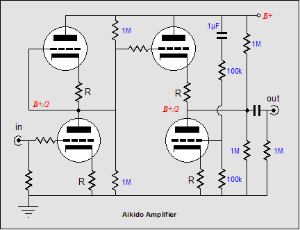
I read recently that high-value carbon comps are pretty noisy and have a 1/f noise characteristic....
I figured I'd ask before trying to tear them all out.
I have a 1M Carbon Comp to ground at both the input and output of my preamp as a safety resistor. Additionally, I use 1M Carbon Comps as the voltage balancers/safety resistors (basically, every place it shows 1M in the image below).
I read recently that high-value carbon comps are pretty noisy and have a 1/f noise characteristic....
I figured I'd ask before trying to tear them all out.
Carbon comp resistors aren't to blame for the LF motorboating, they are effective in HF oscillatory suppression. i.e grid stoppers. 10K is my upper value on grid inputs.
I still use the unmarked 20% types and with a little premeasuring ther'e fine to use.
In your circuit there is still a fundamental design problem. References to power and preamp still remain in texts and seem unclear. Which unit is causing the problem ?
richj
I still use the unmarked 20% types and with a little premeasuring ther'e fine to use.
In your circuit there is still a fundamental design problem. References to power and preamp still remain in texts and seem unclear. Which unit is causing the problem ?
richj
Hi,
At the moment I'm focussing on the pre-amp power supply has being the source of the problem largely based on limited early experiments with different combinations of pre-amp and power amps to narrow down the problematic unit and subsequent suggestions from several helpful posts. (See earlier posts).
At the time the pre-amp appeared to be the problem so most of the experimentation has been carried out on this. I will concede though that I haven't completely ruled out the EL84 PP amp as the culprit since I really don't know any better; (I'm a relative newbie to tube amps so any advice is good advice to me at the moment particularly when troubleshooting. Unfortunately this has probably led to the confusion throughout this thread that you refer to.
I don't think this is an issue as power transformer is rated at 110mA?
OK, tried 9.1V zener in place of 6.2V Zener & also changed 150R to 240R (probably not wise to change two things at once but I could leave R6 as 47k + 1M in parallel). Here are the voltages.
B+ (into Maida Reg) = 268V
Output from Maida Reg = 256V
5687 Anode Voltage = 142V
Voltage across 240R (R5) = 1.4V (Should this be 1.25V?)
Voltage across 47k + 1M in parallel (R6) = 255V.
So, is regulator working correctly now? It looks almost there to me except for voltage of 1.4V across R5
Even so I couldn't resist connecting 5687 preamp (with regulator connected) to EL84 PP amp with no signal and I still have cone movement on both 'speakers!
Where do I go from here? Investigate the power amp... help!
Thanks
Colin
Richj: In your circuit there is still a fundamental design problem. References to power and preamp still remain in texts and seem unclear. Which unit is causing the problem ?
At the moment I'm focussing on the pre-amp power supply has being the source of the problem largely based on limited early experiments with different combinations of pre-amp and power amps to narrow down the problematic unit and subsequent suggestions from several helpful posts. (See earlier posts).
At the time the pre-amp appeared to be the problem so most of the experimentation has been carried out on this. I will concede though that I haven't completely ruled out the EL84 PP amp as the culprit since I really don't know any better; (I'm a relative newbie to tube amps so any advice is good advice to me at the moment particularly when troubleshooting. Unfortunately this has probably led to the confusion throughout this thread that you refer to.
SY: Your regulator isn't.
You may be suffering from one of two problems. First, the regulator draws nearly 10mA with those values. Is that extra load dragging down the raw supply?.
I don't think this is an issue as power transformer is rated at 110mA?
Second, Maida's choice of a 6.2V Zener, while good for minimizing overall dropout, runs the 317 closer to its own dropout voltage. If all else fails, use a 9 or 10V Zener.
OK, tried 9.1V zener in place of 6.2V Zener & also changed 150R to 240R (probably not wise to change two things at once but I could leave R6 as 47k + 1M in parallel). Here are the voltages.
B+ (into Maida Reg) = 268V
Output from Maida Reg = 256V
5687 Anode Voltage = 142V
Voltage across 240R (R5) = 1.4V (Should this be 1.25V?)
Voltage across 47k + 1M in parallel (R6) = 255V.
So, is regulator working correctly now? It looks almost there to me except for voltage of 1.4V across R5
Even so I couldn't resist connecting 5687 preamp (with regulator connected) to EL84 PP amp with no signal and I still have cone movement on both 'speakers!
Where do I go from here? Investigate the power amp... help!
Thanks
Colin
I'm not the original poster of this thread, but I was experiencing the same issue.
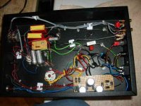
After tearing my hair out, I finally tore out my star ground for my PSU, and rewired it. Previously, I had a bunch of solder tags all tied together with a bolt and nut. I attached each leg of the PSU to a descending tab on the star ground.
Resistance measured across the tags, and from each component negative pin to the ground pin on the power cord, all measured 0V (or as close to 0V as my DVM could measure).
I replaced the solder tag stack with a single tag, with all component grounds all soldered to the same exact point.
My woofer cone movement is gone. Looks like it was a grounding issue for me.
Colin: Hopefully this helps.
Hi,
Good news at last. I finally got the Maida regulator circuit up and running at the weekend. So values used were as follows,
B+ into regulator ~260-265V.
Regulated voltage ~245V
Anode voltage on 5687 at 137V.
Used R5 (on Maida schematic) at 150R & R6 was 47K + 82K in parallel.
Voltage across R5 (150R) was 1.24V.
Connected 5687 pre-amp to EL84 PP power amp without any signal on input and result was no cone movement at all - problem solved
Anyway, thanks to everybody who stuck with me through this problem particularly SY - your advice was much appreciated.
Well back to the next issue of lowering the background hum on the pre-amp......!.
Cheers
Colin.
- Status
- This old topic is closed. If you want to reopen this topic, contact a moderator using the "Report Post" button.
- Home
- Amplifiers
- Tubes / Valves
- Gross loudspeaker cone movement when using tube amps.