Hello all,
I am running a Supratek Chenin preamp which I have modified to use a cascoded IXYS 10M45S CCS on the plate, Cree SiC Schottky Diode bias, and single 2C22 output tubes in a parafeed-type configuration, replacing direct-coupled 6SN7 output tubes (too much gain!). Output transformer is a Lundahl LL1674 and Parafeed cap is 0.56uF. The CCS has 1k gate and anode stoppers already installed.
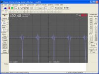
Here's the problem: I am currently installing the Lundahl x-former and am measuring its effect using TrueRTA on my Laptop. When I ran a square wave through the preamp I saw pretty severe ringing on a the leading and trailing edges of a 1kHz square wave (first plot below). There was no grid stopper stock on the 6SN7, but the 2C22 tube has the grid as a top cap, so it needs a longer lead to reach the cap, which is probably exacerbating the problem with stray inductance compared to the 6SN7.
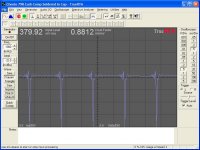
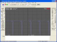
I have tried a series of carbon comp resistors soldered directly to the top cap; plots 2 and 3 below are a 55k and a 79k grid stopper, and in the next post plot 1 is a 100k and plot 2 is a 150k carbon comp - they do decrease the ringing quite a bit.
Calculating the -3dB point using the Miller capacitance of the 2C22 shows a -3dB point of 21kHz with a 100k grid stopper. Based on that I'd rather go with the 79kohm resistor, but there is still some ringing on the trailing edge of the square wave.
The question is: How much ringing is acceptable? I'd like to eliminate it altogether, but not at the expense of frequency response. Any advice is greatly appreciated!
I am running a Supratek Chenin preamp which I have modified to use a cascoded IXYS 10M45S CCS on the plate, Cree SiC Schottky Diode bias, and single 2C22 output tubes in a parafeed-type configuration, replacing direct-coupled 6SN7 output tubes (too much gain!). Output transformer is a Lundahl LL1674 and Parafeed cap is 0.56uF. The CCS has 1k gate and anode stoppers already installed.
Here's the problem: I am currently installing the Lundahl x-former and am measuring its effect using TrueRTA on my Laptop. When I ran a square wave through the preamp I saw pretty severe ringing on a the leading and trailing edges of a 1kHz square wave (first plot below). There was no grid stopper stock on the 6SN7, but the 2C22 tube has the grid as a top cap, so it needs a longer lead to reach the cap, which is probably exacerbating the problem with stray inductance compared to the 6SN7.
I have tried a series of carbon comp resistors soldered directly to the top cap; plots 2 and 3 below are a 55k and a 79k grid stopper, and in the next post plot 1 is a 100k and plot 2 is a 150k carbon comp - they do decrease the ringing quite a bit.
Calculating the -3dB point using the Miller capacitance of the 2C22 shows a -3dB point of 21kHz with a 100k grid stopper. Based on that I'd rather go with the 79kohm resistor, but there is still some ringing on the trailing edge of the square wave.
The question is: How much ringing is acceptable? I'd like to eliminate it altogether, but not at the expense of frequency response. Any advice is greatly appreciated!
Attachments

Last edited:

I tried 1k carbon comps on the grid and they did nothing. I needed to get into the 10s of kohms to see any effect at all. Once in that range, they do seem to stop most of the ringing, and the frequency response still looks very good from 20-20kHz with up to a 100kohm stopper. If the issue is with the transformer, why do the high value grid stoppers seem to work?
I intend to look into lead dress as well - the Supratek preamps are a bit "disorganized" in terms of their point-to-point wiring. They sound very nice, however!
I intend to look into lead dress as well - the Supratek preamps are a bit "disorganized" in terms of their point-to-point wiring. They sound very nice, however!
Last edited:
Hmmmm....
I found the reference linked below which states that:
"The use of a square wave to analyze an amplifier is shown in full in Tremaine’s Audio Cyclopedia, 2nd edition, Audio frequency measurements chapter, pg. 1521, as a means to test the transient response of an amplifier. If the amplifier has ringing at the top of the leading and falling edge, this shows an extremely good high frequency response from the transformer in use."
Am I correct in interpreting this to mean that graph#1 in the first post above is what I WANT the square wave output to look like? If so, then I guess I'm already there without any grid resistors!
Can someone please confirm that this is correct?
Electra-Print.com Tech Blog
.
Hello Magz,
I trust what Jack has to say. I have bought several output transformers from Jack. Correct? No I do not think so. In the link that you provided Jack’s entire point is do not use square waves to test audio devices. The fact that you see ringing under test is not a positive result. What was Jack’s analogy don’t blow backwards through a clarinet you may not like the sound.
DT
All just for fun!
A: Fc just above audio (at 21 KHz) seems absurd for audio and even more so for your test as it does exactly the opposite of what you're trying to achieve. Square wave contains odd harmonics many many levels above the first. This .gif should be animated, it displays square wave generated with first 15 harmonics. Yours, with 19, is just marginally better. Notice remaining ringing at the end of the animation sequence ?
B: Instead of relying on Cmiller to match your expectations (because it usually won't, at least not in real life) you should be using a fixed known value capacitor from grid to cathode.
C: For the sake of discussion, route signal output directly into input (bypassing your amplifier) and run your test again to see whether your sound card is capable of producing suitable square wave in the first place - chances are it might be adding some distortion of its own thanks to finite sample resolution.
Stubs are resonant pieces of transmission line. And if unshielded,
also act as resonant antennas. A grid by itself could be a stub,
and a receiving antenna, and a transmitting antenna, and an
amplifier. And even if shielded from the outside world, its sitting
in an electric field, and a stream of moving electrons modulated
by its own resonances. See where this could become a problem?
Moving electrons is also a Magnetic field. So go figure..
The end impedance of a Beverage longwire antenna might be 450
to 800 ohms. Midpoint impedance of a dipole antenna might be 25
to 50 ohms... If you want to terminate and capture energy from
any antenna into a dummy load, it would need to be somewhere
within this range.
If you make the stopper value too large, instead of de-Q-ing the
problem stub and removing resonant energy. You simply cut the
stub in two high Q pieces that each can resonate. Maybe with a
capacitor now bridged across the gap where you think you have
put a stopper...
If you need a large value resistance to limit a current or prevent
bias pumping, then you still also need small value physically near
the grid, to stop it from behaving as a high Q resonant stub.
Irrelevant trivia factoid: The characteristic impedance of free
space is 377 ohms. Not suggesting this makes ideal stopper.
In a wire, the value could translate 25 to 800. And different
for every frequency vs length. Standing waves are a mess.
Last edited:
First and biggest problem- you're using the wrong tool to measure. Doesn't it strike you as odd that the transformer starts ringing before the impulse?
This is one where a good old fashioned analog scope is the right thing to use, with the source signal coming from a function generator, not the sound card.
This is one where a good old fashioned analog scope is the right thing to use, with the source signal coming from a function generator, not the sound card.
First and biggest problem- you're using the wrong tool to measure. Doesn't it strike you as odd that the transformer starts ringing before the impulse?
This is one where a good old fashioned analog scope is the right thing to use, with the source signal coming from a function generator, not the sound card.
Exactly the right reply!!!
First of all, it is impossible to generate a 1kHz 'square wave' that would actually be square in the sense required for transient measurement with a sound card, because it's bandwidth is strictly limited to a bit less than Fs/2. At 48k Fs, there are only 9 and more likely 8 because of additional analog filtering, odd harmonics to construct the square wave from. Because of this it's transition from edge to level will always show what looks like pre- and post-ringing and is in fact how a bandwidth limited square would normally look - and, there may be additional similar artifacts because of the digital filtering employed at various points, the last stage inside the soundcard DAC.
All of this will aggravate the transformer response, more precisely, if it's not properly loaded/terminated, the 'natural' pre- and post-ringing will show up more severely and will be difficult to correctly diagnose even with an analog scope as a measuring device. If you use a soundcard, things get worse as it's ADCs also have pre-filtering and are also bandwidth limited. In other words, you will see that 'something' is wrong but you simply can't be sure what.
Regarding the grid stopper issue, using very large vakues will upset bias because of grid leak currents. However, that's a minor issue here - grid stoppers are intended to stop TUBES from self-oscillating, and not in mittigating problems with other components in the circuit - instead of attempting to form a filter with difficult to define capacitances (stray capacitances are on the order of tube capacitances!) in order to avoid exciting self-resonance in the transformer, load the transformer correctly, so that they are properly damped in the first place.
Last edited:
Just awoke from my night's sleep to find a lot of excellent information. Thanks, guys!
I suspected that the sound card might be part of the problem. I have access to a nice tectronix function generator and 20MHz scope at work, so I think I'll appropriate them for a night or two and do these measurements right!
For the above measurements, the output was loaded only by the sound card, which has only a 4.4kohm input impedance. The Supratek has a selector switch on the back which allows you to select different resistor loadings for the transformer, starting with none (infinite resistance, where is is now), then a 2.2kohm resistor as the highest resistor value and descending from there. I will play with that as well to see if different loadings have an effect on the ringing.
Sine waves look very nice, by the way, and the frequency response is excellent, with -3dB down at ~13Hz with only the 4.4kohm input impedance of the sound card. That's about twice as good as the stock transformer, which is epoxy potted but appears to be a small toroidal power transformer, 115V+115V:22V+22V, 0.8VA+0.8VA, wired to 4:1 stepdown. Since I'll be running the pre into an EQ unit with 60kohm input impedance, I don't think LF response will be a problem.
Measuring the Lundahl LL1674 with my Escort LCR meter, primaries and secondaries in series for a 4:1 stepdown, I get 190H primary inductance at 100Hz, as opposed to the stock unit's 74H.
OK, I'm officially an idiot!
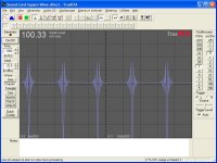
I ran the output of the soundcard directly back into the input, generated a 1kHz square wave, and voila!, the graph below resulted. It looks like the "ringing" I'm seeing may be purely the result of the crappy sound card!
Once I borrow the function generator and scope from work I will know for sure, but it certainly looks like the preamp is faithfully reproducing what I feed into it!
Garbage in, garbage out, as they say...
.
Attachments
Are you actually seeing just the effect of an anti-alias filter before the A-to-D? This will produce ringing from any sharp edge, as the higher frequency components which cancel out the ringing have been filtered away. By adding a big grid stopper you are softening the edge, which gets rid of the ringing. So you may simply be seeing test equipment artifacts. Is your input signal clean, or does that have ringing too?
Let's assume for a moment that the ringing is really there, and would be visible with an analogue scope. The most likely cause is the output transformer. The solution is to damp down the resonance with a snubber, not ruin the frequency response of the whole amp.
If you want to reduce the frequency response, then large grid stoppers is about the worst possible way to do it as it makes the amp response depend on the details of the internal capacitances of the particular valves you happen to have installed.
Stubs and standing waves etc. may be relevant to the true purpose of a grid stopper (stopping VHF/UHF parasitics) but these have nothing to do with audio. Nothing magical happens with a 377 ohm stopper!!
I ran the output of the soundcard directly back into the input, generated a 1kHz square wave, and voila!, the graph below resulted. It looks like the "ringing" I'm seeing may be purely the result of the crappy sound card!
I suspected as much. With propper gear you mentioned you should be getting more meaningful results. Now remember to read the other part of my reply (regarding the ffects of application of LF filtering to square wave signals) before jumping the gun and blaming your transformer once again
")
Will do Arnulf. Thanks for your help and the help of the others on the board - I will occassionally have moments like this as I am still learning my way around tube gear, but you guys are always very helpful!
What did novices like myself do before the internet? Blow up a lot of amps, I suppose!
What did novices like myself do before the internet? Blow up a lot of amps, I suppose!
You are measuring your soundcard response, or whatever it is you're measuring. The pulses (you did not mention anywhere what you are measuring or what the signal source is, other than "square") show ringing characteristic of the sinc(x) function, which rings before the event, a "nonphysical" response. This is typical of sharp filters, like the high order 20kHz lowpass used in sound cards.
Grid stoppers are only intended to address MHz band oscillations, primarily a concern around high transconductance RF tubes. Oscillations in the 100kHz band are due to poor wiring methods, and grid stoppers are not likely to address problems there. Oscillations in the 10kHz band are even further removed.
Tim
Yep, I've got it - adding resistors to the grid does not help here. I have already gone back to simply wiring the input to the top cap, without a stopper. It was an interesting experiment in RC filtering at the tube grid, however - I always like to learn something, even when I'm being a bonehead!
Thanks for the reply, sch3mat1c!
Thanks for the reply, sch3mat1c!
First and biggest problem- you're using the wrong tool to measure. Doesn't it strike you as odd that the transformer starts ringing before the impulse?
This is one where a good old fashioned analog scope is the right thing to use, with the source signal coming from a function generator, not the sound card.
I think that is probably an artifact of the sampling window/algorithm used.. Yes, an analog scope is the proper tool for figuring this out.
Reducing the HF bandwidth of the stage driving the transformer to control ringing in that transformer is not the best thing to do. A snubber across the primary could help, OTOH audio signals are not square waves and getting carried away with damping the ringing may be overkill, and arguably it isn't necessary at all in 0 fdbk applications. Doing so may or may not improve the audible performance.. Make sure that the transformer is loaded as it would be in use before applying any networks to tame the remaining ringing.
A small grid stopper at the grid cap of your 2C22 is appropriate from a stability and EMI standpoint, 1K is more than adequate, and smaller values down to 220 ohms or so are also effective.
Last edited:
Thanks, Kevin.
So soldering a 1kohm Allen-Bradley carb comp resistor at the cap may still be a useful step in terms of EMI rejection and stability. Are you a proponent of carb comps in this position, or do you prefer another resistor type? Carb comps are non-inductive for sure, and since the current is negligible shouldn't contribute much noise; on the other hand they are not very temperature stable and can pick up moisture. Something like a Texas Components Z-foil resistor also has very low inductance, but is extremely temperature stable to boot - at $10 each they are pricey but $10 is not so bad when I only need 2 of them. What do you think?
So soldering a 1kohm Allen-Bradley carb comp resistor at the cap may still be a useful step in terms of EMI rejection and stability. Are you a proponent of carb comps in this position, or do you prefer another resistor type? Carb comps are non-inductive for sure, and since the current is negligible shouldn't contribute much noise; on the other hand they are not very temperature stable and can pick up moisture. Something like a Texas Components Z-foil resistor also has very low inductance, but is extremely temperature stable to boot - at $10 each they are pricey but $10 is not so bad when I only need 2 of them. What do you think?
- Status
- This old topic is closed. If you want to reopen this topic, contact a moderator using the "Report Post" button.
- Home
- Amplifiers
- Tubes / Valves
- Grid Stopper Advice - Graphs Included!