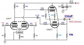
Looking at the schematic I think the problem is that the dc conditions for the output tube are set by the plate voltage of the right hand input tube which is directly connected to the top grid of the output tube. So I would suggest you add a capacitor between the right hand input tube plate and the 100K feeding the grid of the top tube and then measure again.
Cheers
Ian
Cheers
Ian
Hi,
E288CC? Wow...Those valves belong in a shrine. Very rare.
What source are you using as the input for the headphone amplifier?
I was lucky enough to get a pair from a Polish seller a few years ago, they're branded RTC, nice gold pins. I bought them thinking they're a sub for 6DJ8/ECC88...they are, however, very different!
As a source I'm using a simple AD1865 DAC in balanced configuration. In essence, this Broskie amp serves as the IV stage + headphone driver (when I get the circuit figured out....), then volume is controlled via bitperfect arrangement with JRIVER. Theoretically anyway.
Looking at the schematic I think the problem is that the dc conditions for the output tube are set by the plate voltage of the right hand input tube which is directly connected to the top grid of the output tube. So I would suggest you add a capacitor between the right hand input tube plate and the 100K feeding the grid of the top tube and then measure again.
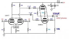
Incredible! Ian, I think you've found an error in Broskie's circuit!
So, you mean install the capacitor as per this diagram (attached)?
Attachments
Hi,
O.K. but how is the I/V conversion done?
As a side note, I'm familiar with the TC circuit as I was looking for a similar balanced to unbalanced convertor for a MC cartridge stage.
Ciao,")
As a source I'm using a simple AD1865 DAC in balanced configuration. In essence, this Broskie amp serves as the IV stage + headphone driver (when I get the circuit figured out....), then volume is controlled via bitperfect arrangement with JRIVER. Theoretically anyway.
O.K. but how is the I/V conversion done?
As a side note, I'm familiar with the TC circuit as I was looking for a similar balanced to unbalanced convertor for a MC cartridge stage.
Ciao,
Ian - you have broken new ground my friend!
I've verified the fault in the circuit. After installing the 0.1uF capacitor as suggested, I re-measured the plate voltages and have 102 to 103 volts across all four plates of the E288CC!
With a 75R bias resistors, the bias is 2.2v, so by my calculations this is running at about 30mA - does this seem correct?
Ian - you have broken new ground my friend!
I've verified the fault in the circuit. After installing the 0.1uF capacitor as suggested, I re-measured the plate voltages and have 102 to 103 volts across all four plates of the E288CC!
With a 75R bias resistors, the bias is 2.2v, so by my calculations this is running at about 30mA - does this seem correct?
OK< looks like we are getting closer. 30mA at 100V is probably too high as it represent 3W of dissipation per anode. We want to be nearer to 20mA. It seems I misread the data sheet. For 20mA at 100V we need 2.5V of bias not 1.5V so the cathode resistors should be 120 ohms rather than 75. Try 120 ohms and measure again.
Cheers
Ian
Ok, readings for 120R: plate voltage is 110v, bias is 2.8v. Seems to be ok, but how do we calculate current if the plate voltage isn't the recommended 100v?
Plate current is simply cathode volts divided by cathode resistance. So you have 2.8/120 amps = 23.3mA. That will do nicely.
Cheers
Ian
Hi,
O.K. but how is the I/V conversion done?
As a side note, I'm familiar with the TC circuit as I was looking for a similar balanced to unbalanced convertor for a MC cartridge stage.
Ciao,
I've simply got some 75R resistors for the i/v stage. The gain stage (input tubes of the broskie circuit) I haven't finalised yet. What is the moost linear nine pin tube with mu > 40? I do recall Ian was doing some testing on 5965 tubes, but found they weren't as 'good' as the ECC88.
Interesting - I've seen that tube's data before. It has higher gain, but similar characteristics to the 12AU7. What resistor values would you use for the LM334 and cathodes on the input stage. Broskie recommends 300R and 6k8 for the 12AU7.
At the moment I'm using the 12AT7 for testing purposes, with 300R and 6k8. Sounds good, but I'm not sure the operating points are correct yet.
At the moment I'm using the 12AT7 for testing purposes, with 300R and 6k8. Sounds good, but I'm not sure the operating points are correct yet.
Hi,
The E80CC I mentioned was for the output stage.
For I/V conversion, think moving coil headamp. You want a low input impedance stage with as low as possible noise contribution of its own.
Explaining how this actually works takes volumes so, if you don't trust me on this or have a shortcut then that's fine by me.
My way is the "if it must be valves" way....
Ciao,
I've simply got some 75R resistors for the i/v stage. The gain stage (input tubes of the broskie circuit) I haven't finalised yet. What is the moost linear nine pin tube with mu > 40? I do recall Ian was doing some testing on 5965 tubes, but found they weren't as 'good' as the ECC88.
1st, why do you think you need a mu greater than 40?
2nd, the most linear tube I know of with a mu over 40 is the 12AX7LPS. The long plate (LP) is the important part and is what leads to the better linearity.
Cheers
Ian
Hi,
The E80CC I mentioned was for the output stage.
For I/V conversion, think moving coil headamp. You want a low input impedance stage with as low as possible noise contribution of its own.
Thanks Frank - do you have an example of a circuit where you've implemented an I/V stage like this?
1st, why do you think you need a mu greater than 40?
The DAC only puts out about 100mVrms with 75R i/v resistors, and so based on some measurements I did with a dB meter, the gain needs to be a minimum of 25dB to get the voltage to the right level to drive the buffer stage (the E288CC circuit we just fixed). The gain of the first stage in Broskie's circuit is [mu/2 + 3dB], hence mu > 40 is the requirement.
2nd, the most linear tube I know of with a mu over 40 is the 12AX7LPS. The long plate (LP) is the important part and is what leads to the better linearity.
Thanks for the idea re the long plate 12AX7. I don't have any 12AX7LPS, but I do have a pair of GE 6072A which are supposed to be quite linear.
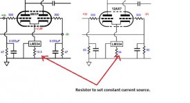
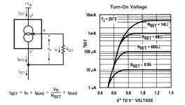
You can see below two example circuits that Broskie gives for I/V stages. I've highlighted the resistor which sets the constant current source (the IC is LM334). He selects 34R for 12AX7, 13R for the 6N1P. This would suggest he's using 1mA plate current for the 12AX7 and about 8mA for the 6N1P.
So, for the 6072A, which has a preferred plate current of 3mA, would the CCS resistor be more like 17R?
Attachments
Last edited:
Hi,
A differential input version of my MC amp stage can be used to achieve that.
It is surprisingly similar in topology to what JB proposes in his Tubecad Journal for a balanced mic preamp (which in turn isn't all that different from a MC pre-pre amp).
Basically it runs the valves in starved voltage, starved current mode which makes them low(ish) input devices, then you run a ccs on the anodes to maximize the gain again.
For that to work you need valves that are happy to run at such low voltage and current.
One that are fine for such application are the EC86, D3A (in triode mode since it's a pentode), ECC88 (not the 6N1P iME which isn't a true ECC88 even if it's been sold us such), ECC288, 6C45P and a few others.
Basically you need to use a valve that shows good linearity when run close to Vg=0.
Are you familiar with "Space charge" valves? Very similar here.
In fact, for what you're using it for, a well filtered and regulated B+ of 24VDC is all you need. The CCS do the rest. Neat and simple and low cost too.
Ciao,
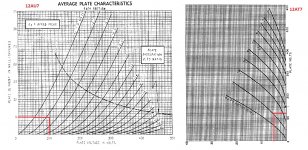
Ok well in relation to the linearity & gain, with the way I have it arranged at the moment, there is a constant current source of 5mA per plate in the gain stage.
So, from testing, a 12AU7 has 100v on the plates, about 2v bias, whereas a 12AT7 has 130v on the plates, about 1v bias. (see attached)
So in order to obtain best inearity with the current CCS circuit (without de-soldering), we need a medium/high mu tube which likes 5mA plate current with plate voltage of 100v to 150v.
Am I thinking along the right lines here, or is this incorrect?
Attachments
Message from John Broskie re: "error in unbalancer"
I normally don't visit here anymore (I was the original poster of Buffalo and Unbalancer thread, the one with the Neohms now gone... Anyway, someone pointed out this to me and I spoke to my friend John B.
He says:
I normally don't visit here anymore (I was the original poster of Buffalo and Unbalancer thread, the one with the Neohms
now gone... Anyway, someone pointed out this to me and I spoke to my friend John B.He says:
Yes, the BCF pushes and pulls, but it does not generate its needed anti-phase signal, thus no reflexive, as it finds the required two-phase signals already presented by the input differential stage. Moreover, do headphones really need to go down below 2Hz? As for the missing cap, it is only missing if you need it. I assumed that some would need it, so I long ago added it to the PCB, as the schematic from the user guide shows:
(image missing)
As I scanned the forum, I note that the wrong input tube is being used, for example a 12AT7 or, worse, 12AX7, as these triodes will not develop enough cathode voltage for the CCS to work well. A low-mu triode, such as the 12AU7 or 6CG7, is needed. On the other hand, with a negative PS rail or with an LT3092, these tubes could be used. Yes, much hacking. "
- Status
- This old topic is closed. If you want to reopen this topic, contact a moderator using the "Report Post" button.
- Home
- Amplifiers
- Tubes / Valves
- Grid resistors -> GND