The impedence of the driver before the grid choke is critically important. Drive it with a 10K source and you can expect to get poor performance, drive it with a 1R solid state preamp and your grid choke is overspec'd by two orders of magnitude. There are also issues with parasitics causing resonances which again are source impedance dependent.
The question is only answerable in respect of the preamp specifications. This is precisely why professional equipment all works to a 600R specification so that you can predict exactly how any two pieces of equipment will interact.
Shoog
The question is only answerable in respect of the preamp specifications. This is precisely why professional equipment all works to a 600R specification so that you can predict exactly how any two pieces of equipment will interact.
Shoog
Last edited:
If you put a resistor in parallel with the grid choke, you'll be lowering the apparent resistance of the load on the preceding stage. In other words, I don't think that would help at all.
You could use a 5687 or 6N6P instead of a 6SN7, and that would give you a lower output impedance into the grid choke, with only slightly less gain and (probably) slightly higher distortion. You'd get better bass response that way.
You can use this handy tool to figure out the -3dB point (F3) of your high pass filter (HPF)...
(Sample)LR Low-pass Filter Design Tool
But a lot depends on exactly how you'll be using the tube, etc. Is this going into a single-ended amp? Push-pull? Preamp of some kind?
--
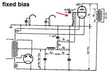
In post five I meant to say adding a resistor on the ground side of the choke. Is this actually a low pass? I mean the signal is not going through the choke. The choke is a shunt for the grid of the AD1 power tube. The AD1 power tube has -74 volts of bias applied in a fixed bias mode. It needs a path to ground. But using a lower value grid resistor would shunt too much of the AC signal from the second stage to ground. I think.
Attachments
Last edited:
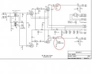
In one datasheet i found, it explicitly shows max grid leak resistor value is 0.4Meg in a circuit that use fixed bias on the AD1. If you're building that Uniamp2, the 6SN7 driver has only 33K plate load. I figured you can use 330K for the grid leak, not needing any grid choke. Am i missing something?
https://frank.pocnet.net/sheets/145/a/AD1.pdf
edit: Pete uses 220K grid leak, even better.
https://frank.pocnet.net/sheets/145/a/AD1.pdf
edit: Pete uses 220K grid leak, even better.
Attachments
Last edited:
In post five I meant to say adding a resistor on the ground side of the choke. Is this actually a low pass? I mean the signal is not going through the choke. The choke is a shunt for the grid of the AD1 power tube. The AD1 power tube has -74 volts of bias applied in a fixed bias mode. It needs a path to ground. But using a lower value grid resistor would shunt too much of the AC signal from the second stage to ground. I think.
It's a high pass filter. Series resistor (the output impedance of the driver tube), shunt choke.
A low pass filter would have series choke, shunt resistor (or capacitor).
--
Last edited:
AJT, is it the same kind of math you use for an interstage transformer?
oh it is a different ballgame...
350 HENRY grid choke?
How many pounds does it weigh?
They're not big, because they don't have any standing current across them (at least not until the output tube draws grid current). Well, they are very big compared to a resistor, it's true.
I don't know if this example is as 'ultimate' as its seller claims, but I think it's representative of the type...
Silk Supermalloy Low DCR Grid Choke Pair | eBay
--
- Status
- This old topic is closed. If you want to reopen this topic, contact a moderator using the "Report Post" button.
- Home
- Amplifiers
- Tubes / Valves
- Grid Chokes