If you wish to commit to clear statement that what I have stated is untrue and not possible according to the basic physical laws governing electronic circuits, to the best of your knowledge, please do so.
I have, several times. In order to make a valid comparison between two coupling methods, the cutoff frequency needs to be held constant. If that's not the case, your suggested comparison is inapt. How many times does that basic fact need to be repeated?
Hi Sy,
Why? Who says it has to?
In a given amplifier, replacing the standard resistor with a gridchoke without other changes (which is how most of those testing gridchokes are doing it and how it is recommended by the manufacturers), results in certain effects.
Let me be clear.
You are claiming that all the effects (including increased output power when using a gridchoke compared to gridresistor) result from lowering F3?
If not, why bring it into this?
Ciao T
I have, several times. In order to make a valid comparison between two coupling methods, the cutoff frequency needs to be held constant.
Why? Who says it has to?
In a given amplifier, replacing the standard resistor with a gridchoke without other changes (which is how most of those testing gridchokes are doing it and how it is recommended by the manufacturers), results in certain effects.
Let me be clear.
You are claiming that all the effects (including increased output power when using a gridchoke compared to gridresistor) result from lowering F3?
If not, why bring it into this?
Ciao T
In a given amplifier, replacing the standard resistor with a gridchoke without other changes (which is how most of those testing gridchokes are doing it and how it is recommended by the manufacturers), results in certain effects.
There's that false premise, yet again. You need to think in a more system-oriented manner, and not focus so tightly on one single component that you lose the overall picture. IMO.
Now, if you have data showing better overload recovery between RC and LC coupling with the same cutoff, by all means let's see it.
You are claiming that all the effects (including increased output power when using a gridchoke compared to gridresistor)
I'd love to see that data, too, again with the same cutoff frequency. You do understand what happens in a transformer as frequencies get lower.
Sy,
Sorry, but that is comparing apples to oranges, if I design two completely different systems. Normally the "apples to apples" comparison is one of "all else unchanged". Under this kind of test regime we can substitute a given part and evaluate the impact this single change has on the system.
You may disagree with the method and refuse to apply it, that does not make it invalid.
In fact, if I elected to show the differences between applying a tweak in a system, randomly let me select a Bybee Quantum Purifier (must be on my mind, how strange) and I insisted I also needed to make many other material changes to the system (say I insist the speakers must be re-positioned) and I then present the measured frequency a with / with Bybee Quatum Purifiers and point to the changes in response as prrof the Quantum Purifiers work, you would severely take me to task and criticise (justly so) my experiment as flawed, as I cannot be sure what I need to attribute the change to.
So I will simply assert that the "all else equal" methode for evaluation is a long established scientifi process and I will use in this context.
Define "better" in the context.
Sy, you understand what happens if we have a choke in a circuit that experiences rectification effects, you understand what the effect will be when the stimulus (rectified current) is removed and you understand why there are flyback diodes on relay coils. So what's the problem?
If so you understand why having a choke in the gridcircuit will deflect the grid positive after repeated short term overload and indeed during permanent overload conditions. Same principles!
Why keep banging about the F3?
There is no need to "see data". We are talking really basic EE101 here, simple principles of the way chokes behave.
Again, the cut-off frequency is entirely immaterial here to anything but timing. The timing we may control in any which way we like, but it makes no real difference to the key change the choke brings.
Ciao T
There's that false premise, yet again. You need to think in a more system-oriented manner, and not focus so tightly on one single component that you lose the overall picture. IMO.
Sorry, but that is comparing apples to oranges, if I design two completely different systems. Normally the "apples to apples" comparison is one of "all else unchanged". Under this kind of test regime we can substitute a given part and evaluate the impact this single change has on the system.
You may disagree with the method and refuse to apply it, that does not make it invalid.
In fact, if I elected to show the differences between applying a tweak in a system, randomly let me select a Bybee Quantum Purifier (must be on my mind, how strange) and I insisted I also needed to make many other material changes to the system (say I insist the speakers must be re-positioned) and I then present the measured frequency a with / with Bybee Quatum Purifiers and point to the changes in response as prrof the Quantum Purifiers work, you would severely take me to task and criticise (justly so) my experiment as flawed, as I cannot be sure what I need to attribute the change to.
So I will simply assert that the "all else equal" methode for evaluation is a long established scientifi process and I will use in this context.
Now, if you have data showing better overload recovery between RC and LC coupling with the same cutoff, by all means let's see it.
Define "better" in the context.
I'd love to see that data, too, again with the same cutoff frequency. You do understand what happens in a transformer as frequencies get lower.
Sy, you understand what happens if we have a choke in a circuit that experiences rectification effects, you understand what the effect will be when the stimulus (rectified current) is removed and you understand why there are flyback diodes on relay coils. So what's the problem?
If so you understand why having a choke in the gridcircuit will deflect the grid positive after repeated short term overload and indeed during permanent overload conditions. Same principles!
Why keep banging about the F3?
There is no need to "see data". We are talking really basic EE101 here, simple principles of the way chokes behave.
Again, the cut-off frequency is entirely immaterial here to anything but timing. The timing we may control in any which way we like, but it makes no real difference to the key change the choke brings.
Ciao T
Sy, you understand what happens if we have a choke in a circuit that experiences rectification effects, you understand what the effect will be when the stimulus (rectified current) is removed and you understand why there are flyback diodes on relay coils. So what's the problem?
Overload recovery time and Q.
Hi Sy,
In a given amplifier, replacing the standard resistor with a gridchoke without other changes (which is how most of those testing gridchokes are doing it and how it is recommended by the manufacturers), results in certain effects.
Ciao T
Hi T,
I am one of those testing gridchokes that replace standard resistor with a gridchoke. In my case I replaced 210k resistor with Silk choke. After experimenting with different coupling cap values I had to switch back due to poor LF performance...
Would you take a look at the schematic of my 300b and give me some suggestions. My topic is here.
Thanks!
Hi, eh, am I right here? I have 4 gridchokes from Stevens and Billington for sale. and they do sound better than grid resistors!
One pair in a µ-can, one wire shortened, middle wire cut, ground wire (found out by listening) long,
or a pair never used, without µ-can... if anybody is interested, please let me know. Depending on the part of the global world, I can make comments if I can send it there...
One pair in a µ-can, one wire shortened, middle wire cut, ground wire (found out by listening) long,
or a pair never used, without µ-can... if anybody is interested, please let me know. Depending on the part of the global world, I can make comments if I can send it there...
It seems to me, based on what little I know, that one advantage of choke plate loading is low noise, which really hasn't been discussed. I would guess that if low noise is a major consideration, then using choke loading on the plate for a medium mu tube would be a good option. I like what this guy has to say about it:
audiofilterchokes-page3
My question though is does it matter what kind of choke is used, outside of specifications for maximum current and inductance. For example, Hammond makes a lot of chokes, like this one:
http://www.tubesandmore.com/products/P-T156C
which is 150H, 8mA (I assume the inductance is good at 60 or so Hz since it is intended as a power supply filter). Would something like this be useful for plate loading a medium mu tube, biased such that it draws less than 8mA? At 16$, I don't see it as a major expense, given that tubes are so $$$ these days. (don't get me started on the older days when you could buy a pile of NOS tubes at less than $1 each)
Last edited:
Here's one example of where choke plate load is supreme: using high transconductance, low Rp tubes in a MC or microphone preamp.
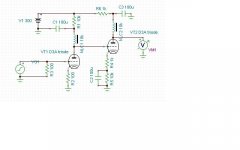
S/N is 105dB, gain is over 70dB, THD is 0.14% (1mV input, 1kHz - distortion goes up at lower frequencies). That is really awesome performance in my opinion. You'd need huge chokes of course, like something from Electra-Print:
Electra-Print.com Plate Chokes & Reactors
S/N is 105dB, gain is over 70dB, THD is 0.14% (1mV input, 1kHz - distortion goes up at lower frequencies). That is really awesome performance in my opinion. You'd need huge chokes of course, like something from Electra-Print:
Electra-Print.com Plate Chokes & Reactors
Attachments
Since the principal advantage of a plate choke is increased swing, and these applications are 1-2V at most, I don't see the advantage of a large, expensive choke versus a simple under-$3 CCS load.
I disagree, obviously. The principal advantage of a choke is NOT necessarily increased swing. They offer a very low noise, high impedance plate load for tubes that require relatively higher DC operating current. A CCS does not typically offer lower noise than a choke, as far as I know. If you know of an example, then please simulate it and show it and prove me wrong rather than just offer an opinion.
I disagree, obviously. The principal advantage of a choke is NOT necessarily increased swing. They offer a very low noise, high impedance plate load for tubes that require relatively higher DC operating current. A CCS does not typically offer lower noise than a choke, as far as I know. If you know of an example, then please simulate it and show it and prove me wrong rather than just offer an opinion.
Remember the old joke about the two guys being chased by the bear? Bear Chase - Animal Jokes - Jokes Place!
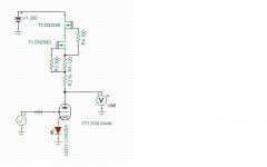
It doesn't have to be lower noise than the choke, it has to be lower noise than the tube after being divided down by the ratio of CCS impedance to rp. And in fact, that's experimentally the case for low rp tubes- see my MC preamp as an example, using a CCS load, where the noise was totally dominated by the first stage tube (a D3a, which is among the quietest).
Remember the old joke about the two guys being chased by the bear? Bear Chase - Animal Jokes - Jokes Place!
It doesn't have to be lower noise than the choke, it has to be lower noise than the tube after being divided down by the ratio of CCS impedance to rp. And in fact, that's experimentally the case for low rp tubes- see my MC preamp as an example, using a CCS load, where the noise was totally dominated by the first stage tube (a D3a, which is among the quietest).
I cannot find your MC preamp after doing a search of this forum. Please provide a reference. Thanks.
Also, this is about facts and evidence. What gain does your MC preamp have, and what is the S/N? I've provided some evidence. If you have something better please show it.
Last edited:
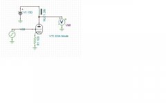
What circuit have you set up and how are you measuring it? My noise matched the tube noise nearly perfectly.
I'm only using Tina right now, so results may not be perfect. I use Spice only to show relative merits of various circuit arrangements. I also do not have a perfect choke spice model, but I think it's perfectly clear that the S/N for the choke plate load is entirely dependent on the DC resistance of the windings.
For your circuit, I see 113dB S/N @ 1kHz.
For the choke plate load (DCR=550ohms, as in the Sowter chokes), I see S/N over 130dB. For higher DCR chokes, S/N is less. The choke version had about the same S/N with an LED in the cathode circuit like your version.
Both versions had very much the same operating point for the tube. The generator was set to zero source impedance.
Now, to be clear, distortion is a lot worse with a choke load, and varies with frequency, so I'm not saying that a choke is a clear winner, only that it can have lower noise.
The spice models I'm using for the transistors come from the manufacturer. The triode connected D3A model I got off of a UK website.
Attachments
- Status
- This old topic is closed. If you want to reopen this topic, contact a moderator using the "Report Post" button.
- Home
- Amplifiers
- Tubes / Valves
- Grid Chokes and choke load