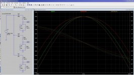
The block diagram on pg 4 shows a few things to think about . . . .
- The passive elements have 2:1 value ratios rather than equal values. I don't recall how this affects harmonic suppression by the Wien network, but I think this increases the gain required from the amplifier. By using an equal-value Wien network the amplifier gain - and, presumably, distortion - can be reduced.
- Decreasing the shunt C (and increasing shunt R) reduces the gain required from the amplifier. Reducing the shunt C by a factor of 2 reduces the required gain from 3 V/V to 2 V/V (3.5 dB). This may reduce the amplifier's contribution to overall system distortion.
- Decreasing the shunt C (and increasing shunt R) also reduces the Wien network's suppression of the harmonic products. Reducing the shunt C by a factor of 2 increases the amount of 2nd harmonic passed by about 0.5 dB; 3rd harmonic by 1 dB.
- Decreasing the series C (and increasing series R) increases the gain required from the amplifier. Reducing the series C by a factor of 2 increases the required gain from 3 V/V to 5 V/V (4.4 dB). This may increase the amplifier's contribution to overall system distortion.
- Decreasing the series C (and increasing series R) also increases the Wien network's suppression of the harmonic products. Reducing the series C by a factor of 2 reduces the amount of 2nd harmonic passed by about 0.5 dB; 3rd harmonic by 1 dB.
Attachments
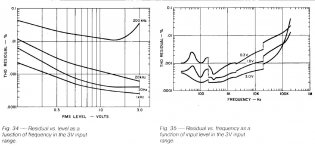
Bob posted scans of his original magazine article at < http://www.cordellaudio.com/papers/thd_analyzer.pdf >. According to Fig 35 (next-to-last page; see atch), the residual THD of the signal source in his analyzer, measured by his analyzer, is about 0.0005% (-104 dB) at 20KHZ with a high output signal level (3V RMS).There is of course also Bob's oscillator, does anyone know which has lower distortion at 20 kHz?
My guess is that most of the residual is created in the analyzer section; the oscillator itself may be 10 dB to 20 dB better. Even if you allow for equal residual contributions from the oscillator and analyzer, the oscillator by itself is not far short of -110 dB.
That's pretty impressive by anybody's standards. Since the Cordell THD Analyzer project was published in 1981, and is still actively discussed today, it passes the criteria of "Don't trust anybody under 30." - so I have started some work aimed at modernizing and improving it.
Dale
Attachments
Since the Cordell THD Analyzer project was published in 1981, and is still actively discussed today, it passes the criteria of "Don't trust anybody under 30." - so I have started some work aimed at modernizing and improving it.
Dale
I'd guess that you've seen this build of Bob's oscillator:
IG-18 #2
Dick seems to find that the HP239A is a bit better than Bob's at 1 kHz, still curious about 20 kHz.
Another build of Bob's oscillator with some upgraded parts, 1 kHz THD = .00018%:
http://www.diyaudio.com/forums/pass...n-analyzer-recomendations-16.html#post1356419
Same with upgraded parts but stock OP amps, 1 kHZ THD = .00019%:
http://www.diyaudio.com/forums/pass...n-analyzer-recomendations-16.html#post1357663
http://www.diyaudio.com/forums/pass...n-analyzer-recomendations-16.html#post1356419
Same with upgraded parts but stock OP amps, 1 kHZ THD = .00019%:
http://www.diyaudio.com/forums/pass...n-analyzer-recomendations-16.html#post1357663
- Status
- This old topic is closed. If you want to reopen this topic, contact a moderator using the "Report Post" button.