I like you more than most of these "yes-sayers"traderbam said:"but the other is more to do with IP protection. "
This is fair enough and I feel the same way. I am also not prepared to give away everything I've struggled to learn in a trice. But I hope myself and others may be excused for asking probing questions and I don't always expect a complete answer.
"My suggestion, Bam, is to build the thing"
Fair enough.
BAM
you make me think
you keep me alert
traderbam
In other words
I like you very much
So much that one day I might build me a traderbam amplifier
remember?
I do
Hi Guys,
Thanks for all the input. It has been wonderful so far.
Nelson (TOAO) and AKSA have really put some serious perspective on the issue of amp design.
Nelson has stated (elsewhere) that the audio experience is, after all is said and done, entertainment.
AKSA has implied as much and basically says that introduction of low order distortion makes amps sound good to the "Audiophile" community.
Both of these designers intentionally sell amps with a sonic signature. And they both apparently do very well indeed since their customers are voting their respective preferences with cash.
The essence of this design excercise is to create a circuit design series and PCB that allows the builder the opportunity to try out a variety of options on one board and therefore discover what flavor he/she likes.
Soon there will be the latest schematic for further comment. I hope you all will continue to contribute to the project.
AKSA,
Thanks for your generous input.
Would you care to share your opinion re: the proper way to to set the driver emitter resistances?
I am uncertain wether Nelson suggested one 100 Ohm resistor from each respective driver emitter to the output or one resistor floating between the driver emitters.
What do you think?
Also, any suggestions for good transistors for the DA, VAS and Driver stages?
Re: More bootstrapping even.
Werback back around '72 in a car-audio BJT amplifier, and it
did indeed work.
I saw this applied by the short-lived but legendary PeterCirclotron said:How about if you also bootstrapped the supplies to the driver transistor collectors too? Say 100 ohms (or less?) from each collector to rail, then a big electrolytic from output to each driver collector.
Werback back around '72 in a car-audio BJT amplifier, and it
did indeed work.
My experience is that it works about the same either way.aborza said:I am uncertain wether Nelson suggested one 100 Ohm resistor from each respective driver emitter to the output or one resistor floating between the driver emitters.


not alwaysAKSA said:Aborza,
I find myself agreeing with the master.....
Hardly surprising, the bugger's always right!!
Cheers,
Hugh
but very often
experience speaks well
Latest Schematics! Long Post!
Happy Hollidays from Florida Y'all,
I hope your Hollidays were great!
I have spent some time putting together all the suggestions from this thread, from personal e-mail and from other net sources. I also grabbed the great simulator demo (http://www.spectrum-soft.com/index.shtm ) and did some operating point studies.
These amps are, I am sure, prosaic by the standards of some of the contributors here. But they should work very well. No fancy foot work. Just simple sturdy circuits that can sound very good.
With some final checks by forum contributors the next step is generating a PCB design that will allow for all the options on both circuits to be implemented as desired.
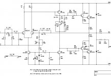
There are two versions. One is a CCS and the other is resistor fed. Both are amenable to "voicing".
Here are some points of interest:
The DA emitter resistors were chosen from suggestions ranging from 100 to 220 Ohms. I split the difference. Within the range suggested there is supposed to be an increased sense of pacing and dynamics.
The same goes for the VAS emitter resistor. I left it out of the resistor fed version because almost everyone suggested it not be used and because, in the resistor fed version, simulations showed that the entire bias for the VAS had to be redesigned with the inclusion of degeneration. It can be left out of the CCS version without any circuit changes.
Base resistors on Q5, 6, 7, and 8 are stoppers. They are there to inhibit parasitic oscillation and are said to improve the perceived reproduction. I suspect that their inclusion allows a smaller Miller cap to be used without introducing instability.
The Q7 and 8 emitter resistor and cap are there to force Class A action in the drivers and to speed up crossover switching so as to lessen crossover distortion. The value was chosen as a "split the difference" decision between suggested values from 100 to 220 Ohms.
The Miller cap is to be adjusted depending on which choices one decides to use in circuit construction. More, less or no emitter degenation will make the difference.
The different boot strap resistor values are said to improve perceived reproduction.
Bias for the DA and VAS were chosed from suggestions. Also my simulations showed that the drivers could pass as much as 100mA under certain conditions and I chose to keep the VAS idle at about 1/10 of that value.
I used the low impedance feedback network because that is what Nelson has used in the past. This results in a lowish input impedance. I would love to hear discussion on this issue, especially in regards to "voicing".
Simulation showed that I could have used 200 Ohm multiturn pots for the offset and bias adjustments and thereby get very fine adjustments. But non-ideal real life components probably will require greater range. So, I chose 500 Ohm multiturn pots.
Rail filtration can be changed, and if desired, left out altogether.
Virtually any change will require adjusting bias and probably offset as well. Therefore, I included adjustment for both.
I noted on simulation that even small offset voltages caused a differential in idle bias currents in Q7 and 8. I suspect therefore, that getting the offset at or very near 0V will improve perceived reproduction. Seems to be a better idea than getting offset down to 50mV or slightly less.
Note the difference in Q7 and 8 emitter resistors in the two circuits. The .57 Ohm resistors are supposed to "voice" better and give the outputs some protection in case of a short. The .1 Ohm resistors are supposed to result in less Class AB distortion from the output stage. Values inbetween are easily implimented. Any thoughts here?
And last, the flyback protection diodes can also be left out. I do not know the audible effects of their inclusion, but they are absent in many designs. Any thoughts or comments?
Take a look at the schematics and tell me what you think. Give me suggestions. And check out what I have said here to be sure I am on the right track.
I need all the help I can get.
The schematics follow.
Happy Hollidays from Florida Y'all,
I hope your Hollidays were great!
I have spent some time putting together all the suggestions from this thread, from personal e-mail and from other net sources. I also grabbed the great simulator demo (http://www.spectrum-soft.com/index.shtm ) and did some operating point studies.
These amps are, I am sure, prosaic by the standards of some of the contributors here. But they should work very well. No fancy foot work. Just simple sturdy circuits that can sound very good.
With some final checks by forum contributors the next step is generating a PCB design that will allow for all the options on both circuits to be implemented as desired.
There are two versions. One is a CCS and the other is resistor fed. Both are amenable to "voicing".
Here are some points of interest:
The DA emitter resistors were chosen from suggestions ranging from 100 to 220 Ohms. I split the difference. Within the range suggested there is supposed to be an increased sense of pacing and dynamics.
The same goes for the VAS emitter resistor. I left it out of the resistor fed version because almost everyone suggested it not be used and because, in the resistor fed version, simulations showed that the entire bias for the VAS had to be redesigned with the inclusion of degeneration. It can be left out of the CCS version without any circuit changes.
Base resistors on Q5, 6, 7, and 8 are stoppers. They are there to inhibit parasitic oscillation and are said to improve the perceived reproduction. I suspect that their inclusion allows a smaller Miller cap to be used without introducing instability.
The Q7 and 8 emitter resistor and cap are there to force Class A action in the drivers and to speed up crossover switching so as to lessen crossover distortion. The value was chosen as a "split the difference" decision between suggested values from 100 to 220 Ohms.
The Miller cap is to be adjusted depending on which choices one decides to use in circuit construction. More, less or no emitter degenation will make the difference.
The different boot strap resistor values are said to improve perceived reproduction.
Bias for the DA and VAS were chosed from suggestions. Also my simulations showed that the drivers could pass as much as 100mA under certain conditions and I chose to keep the VAS idle at about 1/10 of that value.
I used the low impedance feedback network because that is what Nelson has used in the past. This results in a lowish input impedance. I would love to hear discussion on this issue, especially in regards to "voicing".
Simulation showed that I could have used 200 Ohm multiturn pots for the offset and bias adjustments and thereby get very fine adjustments. But non-ideal real life components probably will require greater range. So, I chose 500 Ohm multiturn pots.
Rail filtration can be changed, and if desired, left out altogether.
Virtually any change will require adjusting bias and probably offset as well. Therefore, I included adjustment for both.
I noted on simulation that even small offset voltages caused a differential in idle bias currents in Q7 and 8. I suspect therefore, that getting the offset at or very near 0V will improve perceived reproduction. Seems to be a better idea than getting offset down to 50mV or slightly less.
Note the difference in Q7 and 8 emitter resistors in the two circuits. The .57 Ohm resistors are supposed to "voice" better and give the outputs some protection in case of a short. The .1 Ohm resistors are supposed to result in less Class AB distortion from the output stage. Values inbetween are easily implimented. Any thoughts here?
And last, the flyback protection diodes can also be left out. I do not know the audible effects of their inclusion, but they are absent in many designs. Any thoughts or comments?
Take a look at the schematics and tell me what you think. Give me suggestions. And check out what I have said here to be sure I am on the right track.
I need all the help I can get.
The schematics follow.
Attachments
Re: Latest Schematic II.
I would remove the 500Ohm pot on the base of Q3. Why? When you adjust the offset, which will be low without an adjustment because of a gain of x1 at DC, you will also adjust the openloop gain of the amplifier. Try to calculate the base resistor on Q3 more accurate, and you will have a offset like +/- 50mV and very little spreading in GPBW of the amplifiers you build.
Everything else looks good....
A small suggestion is to replace the two bias diodes with a single LED. A LED has the same voltage drop over temperature as a BJT.
This will give you a more constant current source over temperature range.
I hope this become handy.
PS:Not far away from a NAIM amp shown at http://www.neilmcbride.co.uk/
Sonny
aborza said:Here is the CCS version.
The 475 Ohm resistor on Q10 comes from Nelson's A40. He says it helps with negative rail clipping. I believe him.
Please tell me what you think.
All suggestions are welcome.
E-mail me if you like.
I would remove the 500Ohm pot on the base of Q3. Why? When you adjust the offset, which will be low without an adjustment because of a gain of x1 at DC, you will also adjust the openloop gain of the amplifier. Try to calculate the base resistor on Q3 more accurate, and you will have a offset like +/- 50mV and very little spreading in GPBW of the amplifiers you build.
Everything else looks good....
A small suggestion is to replace the two bias diodes with a single LED. A LED has the same voltage drop over temperature as a BJT.
This will give you a more constant current source over temperature range.
I hope this become handy.
PS:Not far away from a NAIM amp shown at http://www.neilmcbride.co.uk/
Sonny
sonnya -thanks for the link
this is the "naim style" amp sonnya means
It can be good to study it, and compare.
Note that he suggest alternative LED or diodes
the output uses 2 NPN
see Notes!
Neil's Naim style amplifier PDF
this is the "naim style" amp sonnya means
It can be good to study it, and compare.
Note that he suggest alternative LED or diodes
the output uses 2 NPN
see Notes!
Neil's Naim style amplifier PDF
Attachments
To anyone building the bootstrap cap version, I would recommend adding a clamp diode to the base of the driver transistor. See D3 in the link.
http://k-amps.8m.com/cgi-bin/i/PowerAmps/Semicond/cit12.jpg
One 'never' thinks he will drive the amplifier into clipping. In reality a clamp diode will improve sound quality by keeping the devices from being driven into hard saturation.
The APT Model 1 could be driven about 10dB into clipping as observed on an oscilloscope before it became 'nasty sounding'. It used a Baker clamp so the front end which ran from a high voltage tier could not saturate the output stages.
The Yamaha M40 of the same vintage, and with the identical output stage topology, sounded better at low volumes. But at high volumes it just 'fell apart'.
Even though of similar power, the APT would subjectively play twice as loud.
#51 is just like the Pass A40 with discrete outputs and drivers (omitting the Q11 j-fet and D3). The only other real difference is the bootstrapped input impedance on the A40.
I have built several with ±57V~±95V, and three to six pair of outputs.
Alas, the $6 A40 board in no longer in stock at AudioXpress.com (although I may have a couple floating around).
I have built several with ±57V~±95V, and three to six pair of outputs.
Alas, the $6 A40 board in no longer in stock at AudioXpress.com (although I may have a couple floating around).
Re: Latest Schematic II.
"Help" with negative rail clipping can be an understatement here. I've had one too many amps go into latch-up - and not just for a mircosecond or two - if that stopper is omitted.
aborza said:
The 475 Ohm resistor on Q10 comes from Nelson's A40. He says it helps with negative rail clipping. I believe him.
"Help" with negative rail clipping can be an understatement here. I've had one too many amps go into latch-up - and not just for a mircosecond or two - if that stopper is omitted.
Re: Re: Latest Schematic II.
And that pot is in a very very bad place for noise to be generated. With pots you have to deal with other sources besides Johnson noise. In a worst case, that wiper could go open and Q3 saturates. Ouch. Just the usual dust and vibration can make it sound like anything from dead air FM hiss to thunder. It won't do it right away, but can over time.
If you want a trimmable resistor, put several in parallel and selectively remove.
sonnya said:
I would remove the 500Ohm pot on the base of Q3. Why? When you adjust the offset, which will be low without an adjustment because of a gain of x1 at DC, you will also adjust the openloop gain of the amplifier. Try to calculate the base resistor on Q3 more accurate, and you will have a offset like +/- 50mV and very little spreading in GPBW of the amplifiers you build.
And that pot is in a very very bad place for noise to be generated. With pots you have to deal with other sources besides Johnson noise. In a worst case, that wiper could go open and Q3 saturates. Ouch. Just the usual dust and vibration can make it sound like anything from dead air FM hiss to thunder. It won't do it right away, but can over time.
If you want a trimmable resistor, put several in parallel and selectively remove.
- Status
- This old topic is closed. If you want to reopen this topic, contact a moderator using the "Report Post" button.
- Home
- Amplifiers
- Solid State
- Greening a Classic?