Hi,
I am building a new preamp for my studio, so I made a new board for this pre which has pin connectors to allow for different base-boards and even different kinds of premps.
So please comment on my design, especially possible ground loops and other power-related problems.
Thanks
edit: some problems with ISP...
Attachments
kubeek said:...So please comment on my design...
You mean: "Those of you with 'Eagle' installed..."
Is it so hard to post a a decent .gif ?
Re: Re: Green Pre board - modular
If you download "screenhunter" you will be able to capture the window to a jpg or a gif etc
juma said:
You mean: "Those of you with 'Eagle' installed..."
Is it so hard to post a a decent .gif ?
If you download "screenhunter" you will be able to capture the window to a jpg or a gif etc
kubeek said:
I am building a new preamp for my studio, so I made a new board for this pre which has pin connectors to allow for different base-boards and even different kinds of premps.
So please comment on my design, especially possible ground loops and other power-related problems.
Thanks
Greg Erskine said:Eagle 4.16 won't open the files.
My Eagle took kubeeks files ( .brd and .sch )
I did a Screen Capture & here is the schematic ( 7 kB .png )
So ..... Comments for kubeek's work, Please!
")
Lineup
I call this first version:
GreenPre_kubeek-080617a.png
( 2008 June 17, version a )
Attachments
Re: Re: Re: Green Pre board - modular
Sure, but you still have to have EAGLE installed to capture anything...
This PCB screams trouble on top of the lungs - there is so much stray capacitance and inductance on it that you can easily turn it into wide-band transceiver.
Kubeek, search the forum and look at the works of the more experienced members - you'll learn a lot
nigelwright7557 said:
If you download "screenhunter" you will be able to capture the window to a jpg or a gif etc
Sure, but you still have to have EAGLE installed to capture anything...
This PCB screams trouble on top of the lungs - there is so much stray capacitance and inductance on it that you can easily turn it into wide-band transceiver.
Kubeek, search the forum and look at the works of the more experienced members - you'll learn a lot
Re: Re: Re: Re: Green Pre board - modular
No ! I meant he has to use screenhunter !
Screenhunter will capture his window and send it to a jpg file for our perusal !
juma said:
Sure, but you still have to have EAGLE installed to capture anything...
This PCB screams trouble on top of the lungs - there is so much stray capacitance and inductance on it that you can easily turn it into wide-band transceiver.
Kubeek, search the forum and look at the works of the more experienced members - you'll learn a lot
No ! I meant he has to use screenhunter !
Screenhunter will capture his window and send it to a jpg file for our perusal !
Re: Re: Re: Re: Re: Green Pre board - modular
Right you are ! It's just that you quoted my post
nigelwright7557 said:
No ! I meant he has to use screenhunter !
Screenhunter will capture his window and send it to a jpg file for our perusal !
Right you are ! It's just that you quoted my post
Re: Re: Re: Re: Re: Re: Green Pre board - modular
Apologies...........
juma said:
Right you are ! It's just that you quoted my post
Apologies...........
Re: Re: Re: Re: Green Pre board - modular
I think this is a bit hard...
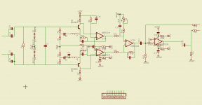
Schematic.
The positive end of C14 is not connected to anything in the schematic. Agnd symbols are incorrectly oriented. The connector is not connected to anything. Labels are superimposed and illegible. Inputs and outputs are not clearly indicated.
This makes it a bit difficult to evaluate the PCB.
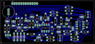
PCB
Silkscreen lables are illegible. Tracks are higgledy-piggledy and unmitred. Ugly.
It's better to keep inputs away from outputs and away from power connections if physically possible. This also makes for a sensible signal path. Not that I'm saying yours isn't, it's just a lot of trouble to go through it component by component especially when you can't read the labels.
Try to keep your tracks horizontal, vertical or at 45 degrees. This is just good practice. Mitre all corners where possible. Never create an internal angle <90 degrees. Look at any motherboard...
65/100
w
juma said:
This PCB screams trouble on top of the lungs - there is so much stray capacitance and inductance on it that you can easily turn it into wide-band transceiver.
I think this is a bit hard...
Schematic.
The positive end of C14 is not connected to anything in the schematic. Agnd symbols are incorrectly oriented. The connector is not connected to anything. Labels are superimposed and illegible. Inputs and outputs are not clearly indicated.
This makes it a bit difficult to evaluate the PCB.
PCB
Silkscreen lables are illegible. Tracks are higgledy-piggledy and unmitred. Ugly.
It's better to keep inputs away from outputs and away from power connections if physically possible. This also makes for a sensible signal path. Not that I'm saying yours isn't, it's just a lot of trouble to go through it component by component especially when you can't read the labels.
Try to keep your tracks horizontal, vertical or at 45 degrees. This is just good practice. Mitre all corners where possible. Never create an internal angle <90 degrees. Look at any motherboard...
65/100
w
Re: Re: Re: Re: Re: Green Pre board - modular
Thanks for all the input, now to the details:
Silkscreen lables are illegible are just how they came after placing the components, they are not meant to be printed on the board yet.
I understand it is hard with that (no) labeling, so I will try better next time.
Why not <90degrees angles? And why there should be only multiples of 45?
It seems to me that any angle will carry current, which is the main concern.
Thanks for all the input, now to the details:
The in fact are connected, but to make the schematic readable they are only connected by nets, not visibly by wires.wakibaki said:
The positive end of C14 is not connected to anything in the schematic. Agnd symbols are incorrectly oriented. The connector is not connected to anything. Labels are superimposed and illegible. Inputs and outputs are not clearly indicated.
Silkscreen lables are illegible are just how they came after placing the components, they are not meant to be printed on the board yet.
wakibaki said:
It's better to keep inputs away from outputs and away from power connections if physically possible. This also makes for a sensible signal path. Not that I'm saying yours isn't, it's just a lot of trouble to go through it component by component especially when you can't read the labels.
I understand it is hard with that (no) labeling, so I will try better next time.
Why not <90degrees angles? And why there should be only multiples of 45?
It seems to me that any angle will carry current, which is the main concern.
Re: Re: Re: Re: Re: Re: Green Pre board - modular
Not on the schematic I saw. Am I supposed to guess?
I need to see the labels so I can tell which component is which.
That is the main concern. Your board is probably quite useable, although to be sure I would prefer to be able to see how close capacitors are to their chips without a big effort.
Most PCB's are produced by chemical etching. Tight corners can trap etch solution even after washing and cause problems years later.
Keep lines straight or at 45 degrees. This will make angles <90 less likely to occur and encourages a disciplined approach which may be more critical if, for example, you need to route a 16-bit bus. If your lines are straight then the spacing is less of a problem. Miter corners habitually, it generally makes little difference below RF but again, it's a good habit to get into.
Be careful with your clearances when taking tracks between pins.
Look at a PC mainboard. This will show you the standard expected of a modern PCB layout person. It's not difficult to achieve with software.
w
kubeek said:The in fact are connected, but to make the schematic readable they are only connected by nets
Not on the schematic I saw. Am I supposed to guess?
kubeek said:Silkscreen lables are illegible are just how they came after placing the components, they are not meant to be printed on the board yet.
I understand it is hard with that (no) labeling, so I will try better next time.
I need to see the labels so I can tell which component is which.
kubeek said:Why not <90degrees angles? And why there should be only multiples of 45?
It seems to me that any angle will carry current, which is the main concern.
That is the main concern. Your board is probably quite useable, although to be sure I would prefer to be able to see how close capacitors are to their chips without a big effort.
Most PCB's are produced by chemical etching. Tight corners can trap etch solution even after washing and cause problems years later.
Keep lines straight or at 45 degrees. This will make angles <90 less likely to occur and encourages a disciplined approach which may be more critical if, for example, you need to route a 16-bit bus. If your lines are straight then the spacing is less of a problem. Miter corners habitually, it generally makes little difference below RF but again, it's a good habit to get into.
Be careful with your clearances when taking tracks between pins.
Look at a PC mainboard. This will show you the standard expected of a modern PCB layout person. It's not difficult to achieve with software.
w
Re: Re: Re: Re: Re: Re: Re: Green Pre board - modular
Anyway, here is a newer version, I mostly moved labels for readability, and did some 45 degrees corners.
You were supposed to use Eagle and open the board and schematic, I didn´t post those pictures...wakibaki said:
Not on the schematic I saw. Am I supposed to guess?
Anyway, here is a newer version, I mostly moved labels for readability, and did some 45 degrees corners.
Re: Re: Re: Re: Re: Re: Re: Re: Green Pre board - modular
I did post those pictures.
Me did it.
To try my best to support an old audio fiend ( Your Headhone amplifier, remember? )
Try to be helpful. Do a favour.
Maybe I shouldnt have .. but this puts the question how many comments you would have gotten, kubeek, if I had not tried to help you.
Did I expect any thanks, or positive comment from you by posting schematic images?
Maybe I did ..
But I have learned well, by now, how we ( and some ) people are.
We shouldnt expect nothing. Not on the positive sides.
Should we
... wonders Lineup June 2008
kubeek said:[B
I didn´t post those pictures...[/B]
I did post those pictures.
Me did it.
To try my best to support an old audio fiend ( Your Headhone amplifier, remember? )
Try to be helpful. Do a favour.
Maybe I shouldnt have .. but this puts the question how many comments you would have gotten, kubeek, if I had not tried to help you.
Did I expect any thanks, or positive comment from you by posting schematic images?
Maybe I did ..
But I have learned well, by now, how we ( and some ) people are.
We shouldnt expect nothing. Not on the positive sides.
Should we
... wonders Lineup June 2008
I didn´t mean it like that at all.lineup said:
I did post those pictures.
Me did it.
To try my best to support an old audio fiend ( Your Headhone amplifier, remember? )
Try to be helpful. Do a favour.
Maybe I shouldnt have .. but this puts the question how many comments you would have gotten, kubeek, if I had not tried to help you.
Did I expect any thanks, or positive comment from you by posting schematic images?
Maybe I did ..
But I have learned well, by now, how we ( and some ) people are.
We shouldnt expect nothing. Not on the positive sides.
Should we
... wonders Lineup June 2008
I was just saying that people (wakibaki) can´t blame me for ilegible schematic, when I didn´t post it.
Anyway, sorry for the delay because my internet is dead and won´t be back soon.
So any comments to the updated board?
Attachments
- Status
- This old topic is closed. If you want to reopen this topic, contact a moderator using the "Report Post" button.
- Home
- Amplifiers
- Solid State
- Green Pre board - modular