I never bothered to work out Rob's box as have no mobility, nor way to cut anything accurately
here it is in proportion so you can figure out the width and maybe resonance - I think that was an 18" driver but have to look
http://img78.imageshack.us/img78/659/infrard1.gif
here it is in proportion so you can figure out the width and maybe resonance - I think that was an 18" driver but have to look
http://img78.imageshack.us/img78/659/infrard1.gif
Rob made an interpretation which IIRC didn't go out of the gap at 1KW input - question - did it do something out of the ordinary? - apparently it had some output to around 15hz
Freddi
Looks like his inside width is 62cm or 24" & it is an 18" woofer. I came up with a resonator volume of .070308 meter^3. With the port length it looks like the band width should be 28.175Hz to 68.742Hz
I understand that, but I think real world measurements are going to fall right in between your predicted high and low cutoff. So far it's the best guess using actual math and your numbers certainly are making sense. Your numbers might not correspond exactly to real measurements but I don't think you are too far off.
The fact that there are 3 different size options, and a random driver provides favorable (if not perfect) results shows that the designer had great understanding of what he was doing.
TwisterZ is currently taking the theory to the nextstep and predicting (very accurately, I believe) how the box will respond with the use of readily available resonator calculators. I'm not sure Bibster's box has quite the range predicted, but it's definitely in the ballpark.
Hi,
From my point of view I don’t agree with the statements above but this doesn’t disqualify me or any other person that is of suspicious nature to be in doubt when reading this tread and I think many are when reading the extraordinary conclusions sometimes made in this tread.
Twisters end correcting calculations is only correct to use when appropriate and will not be correct if used at the junction of X, X’, Y where the 3 cm to at most 4.5 cm high battens are placed between panel B and C.
The end correcting factors are acting interwoven together with the very close areas as shown in the Wilmslow Audio Holliman paper.
This will certainly show up when measuring f –3 dB for any of the Wilmslow boxes in open air.
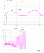
I haven’t seen the slightest suspicion of infra sound in the GH-1.wave sample given in post # 131.
I wouldn’t even call this a sample of a ‘good in the ballpark’ sub as the cut-off is just below 30 Hz where the signal is distorted and noisy.
Anyone with an oscilloscope or a spectrum analyzer can examine the signal content in GH-1 wave and is then not fooled by ear judging nonexistent infra sound that in the reality shows up as noise instead of real infra sound.
See attached picture 1 showing the most important signals from GH-1.wave.
My first Holliman simulation and practical tests went at least 10 Hz lower and only acted like a band pass filter and probably very similar to what Freddie pictures of a velocity coupled sub does, not with the ambition as the Holliman paper suggests, the ability to work in the infra sound region.
I’ve also been looking trough the Holliman patent paper further and I will show what I found relevant or not.
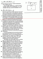
Look at picture 2. The text under the red line together with picture ‘D/’ is in my opinion partly not valid or is working erratically if the tube x’ especially is short as in G/.
My first test and findings using MJK: s program is still relevant and only valid with the text above the red line and for the set-up as in picture D/ because the ‘explanations’ in the text further down calls for a new arrangement of Holliman cabinet layout like the drawings in picture 3.
This is not pointed out clearly in the patent paper when the patent owner writes about phase lag effects and anyone who have read the paper step by step, as I did, can understand what I’m pointing at.
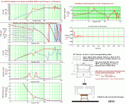
The conclusions I have drawn from the picture 3 or G/ is that for this cabinet no secure PLL like ‘lock- in’ will occur as a phase aligned result over the whole port bandwidth and extension into the infra region.
This ‘lock-in’ is not even securely mantained for infra signals when the load is equipped with just long enough tapered ports, X’, as the use of short widening tapered ports as in picture 3 is counteractive to a correct load for producing infrasound.
I think Holliman fiddled with the X’ tapering and noticed how fragile this pivot point was for the so-called ‘lock in’ action and extension to infrasounds.
Even small room attributes, like an open door could affect the operation he wanted to be maintained.
The acoustic phase for the X’ ports is simply normally lagging 180 degrees, velocity coupled or not with respect to the driver in the infra region.
Only port frequencies over about 22 Hz in picture 3 are in phase and augmented by the output from the Helmholtz volume thus when 0 degree phase difference exists.
This is also in line with what I found the GH-1.wav sample. Look at picture 3, the second plot, no infra signal whatsoever.
The only way to secure extension down to the infra region is to increase the length of X’ or by using the opposite counteractive length tapering, I also find is valid for this case.
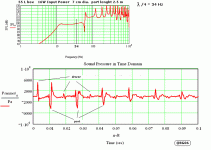
This makes unfortunately the speaker not a reproducer anymore but rather a… producer… of sound as the initial perfect transient is later followed by a delayed low Q higher-level variant, this causes low frequency ‘ringing like a bell’ sounds for hundreds of mS if not tapered with widening ports as in picture 3.
Otherwise this will be the case: picture 4, the transient response for my driver in a 55 L box but with one 100” straight port in a very similar box as in the Wilmslow paper.
I have 2 Holliman boxes to be examined in the pipeline, the first as picture 3 will probably be discarded due to the flaws I found but a new net 223 L sectioned box will hopefully be put together this weekend equipped with a old driver ‘Sinus 25WBA12,4BP8’.
I still have a couple of those drivers and this box will be put together and measured with help of a friend in his DIY workshop.
B
Attachments
cool - will be interesting to see result vs what can be done in same bulk with other type.
wasn't there a subjective comment on the Holliman to effect that the effect took some time to "build up"?
perhaps sometime you might look at a Karlson? - problems include getting them fairly smooth w/o too much honk, effective reflector, and perhaps some control of 3rd Z peak in vented cases. Freddy
Bjorno, I have to give you credit. I didn't think this design could be modelled with existing software, but I think you are creating an accurate picture of what we are hearing. But I do not agree that noise is inherent in the design.
You didn't expect the 10 inch version to get down to 5 hz, did you? The patent makes no mention at all of 5 hz. It mentions the 15 inch version got to 7 hz with little loss of volume. It is the doc with the plans that mentions 5 - 25 hz and that is the catchphrase I have been referring to so often. How much can you expect from a 10 inch driver? I was expecting a bit lower than 22 hz (referring to attachment 3), maybe 15 hz or so, but certainly not 5 hz from the 10 inch box.
Also referring to attachment 3, the tuning range is obviously from about 22 hz and up, which, on the second graph looks like a phase lock, as I understand it, as the blue and red line overlap. That means that the phase matches over it's entire usable range, even if the range isn't as much as expected. Actually your current work seems to prove that this design works, although the 10 inch version may be tuned a bit high.
So the 10 inch version isn't an infrasonic powerhouse. This is not really big news to me, although I think a 15 hz f3 is possible with the correct driver and using the plans. And with small mods, such as in attachment 4, a single 10 inch driver is putting out levels of over 95 db down to 10 hz with only 16 watts. What other design can claim those numbers?
I never realistically expected any more than a 7 hz f3 from the 15 inch version following the plans. According to TwisterZ's predictions, that might even be a stretch. But as far as I can tell, this is the most space efficient, cost effective way to get a 7 hz f3.
Such a pity that I don't have accurate T/S parameters for my driver. In that case, I could've simulated something like a BR or so, te predict its response.
We could've then compared that to some (yet to be made) proper measurements (for as far I'm able to) of my GH box.
I could try to fit a KEF B139 (sp1044) on it as well...
Personally, I think/feel, this box does indeed go very low. Lower than anything I made so far WITH THIS PARTICULAR DRIVER.
I'll see if I can manage to get a hold of some electret(s) to do this measurements. I might even squad my little boy's room (4*4m) and condemn the door (for as far as possible) and do some tests with the windows closed/open. I'll use the proposed samples, a quite ordinary Yamaha amp, and a CD player.
I'll just record the microphone's signal, and make it availible to you.
Any ideas about Mic. placement?
Paul
maybe keep mic 3 feet away and on floor assuming your coupler's mouth is facing forwards, and for testing unplug noisy appliances such as refrigerator - don't forget to turn them back on after the test. do you have a software generator to do single sine tones? - may be useful although room will add overtones but speaker is intended for room.
Freddi this design you introduced what additional information do you have on it?
Is bibster the only one that is building anything toward the GH design?
I have not taken enough interest in this design but I am just starting to read through the posts now as I have time. It will interesting where you all take this while I slowly figure out what you are all working on.
Thanks Just a guy for the heads up... or I think its you anyway.
Gexter
Gex,
The natural progression should have been from BassBoy to BassMan, but since there's much more expertise on this board, he decided to be Just a Guy. If I felt a name change was needed, I would have stepped down to BassBaby. When he gets one of these GH things understood and working properly, then he'll evolve straight to BassMan.
The natural progression should have been from BassBoy to BassMan, but since there's much more expertise on this board, he decided to be Just a Guy. If I felt a name change was needed, I would have stepped down to BassBaby. When he gets one of these GH things understood and working properly, then he'll evolve straight to BassMan.
What's in a name? In my case...not much. I found this forum a few months ago while searching for information on Danley's Tower of Power. Without membership I could read the text, but could not see Qi's renderings (attachments). To my surprise, my usual forum name was already taken. So were my next 10 attempts at a username. I really wanted to see the pictures, so I kept typing random words until it finally let me in.
Bibster is the only one that has a working model of the plans so far in this discussion. TwisterZ has made plans for a much larger version for an 18 inch driver which may have much greater exension than the original. Bjorno has expressed interest in building this box and testing it in a lab setting but got off to a bad start with the wrong diagram. Since then, he has found the plans and can now apparently model this design using MJK's spreadsheets. I'm not familiar with MJK's software and I don't know exactly how Bjorno is doing it but it looks like his sims are accurate, which is a HUGE breakthrough. It could mean no more guessing about anything.
At this point it seems that the 3 different sizes of this box are all tuned a bit higher than expected but we know that longer port X1 = lower low end cutoff. This is shown clearly in Bjorno's attachment 4 of his last post in which (I assume) he modelled his 10 inch Peerless XLS in a Holliman type enclosure with much longer straight ports. The response curve is just lovely, not incredible extension, but the usable part is very flat and the bump at the bottom is not too pronounced.
If it turns out that Bjorno's work with MJK's software can truly accurately, consistantly predict response then the cavity volume, length and shape of ports and the driver selection can be all be tailored to provide the required range of response and to make sure that response is relatively flat over that range.
Are there other ways to get as low as the Holliman box in the plans? Especially considering that the boxes in the plans are not tuned as low as first expected, the answer is yes. With today's low fs drivers, IB, or ripole (as suggested by Moray), or a half wave, closed, half SD straight pipe (as suggested by GM), and a couple of other designs qualify. But none of these other designs exhibit the sensitivity of the Holliman box, or the impression that (without EQ) response seems to get stronger as it gets lower.
Bjorno has suggested that noise is inherent in this design, and has included attachment 1 of his last post to show that response is not a pure sine, but it is spiky and noisy as it follows the wave. Is this interferance from the unboxed side of the driver or something else? Either way, I'm sure it can be controlled.
It is looking like extremely long ports are the key to infrabass with this design. Boxes larger than the ones in the plans may be needed for true, unattenuated extension down to 5 hz, although I'm sure the 15 inch version from the plans will be more than enough for most people.
At this point it is probably silly to build without modelling the results first. I don't have MJK's software. Bjorno seems far too busy to do a bunch of simulations with different drivers and ports. Is there anyone else with the software that wants to try to optomize the 15 inch version for extended, flat response with a given driver? I will build as soon as possible but a lovely response on paper certainly won't hurt.
- Home
- Loudspeakers
- Subwoofers
- Graham Holliman Velocity Coupled Infra Bass Speaker?


