You took one for the team.
"Throat velocity like that is going to squeal like a little piggy" seems to be the operating principle for the low frequency "velocity coupled" whistle effect .
Both your sim and Charlie's RTA show nothing much audible from this design down low, but a LF "whistle" in the right room could be the artifact that has generated interest, and that whistle noise probably is generated just as effectively by a high Fs low Xmax cone as a "modern" low FS high Xmax driver.
Art
That "whistle" noise is going to sound like port chuffing, isn't it? I can't say for sure but I'm thinking about trying this to see how bad it sounds by taking a high excursion 15 inch driver and screwing it down onto a flat board firing it through a 3 inch hole.
Even if the long ports mask the chuffing the simulation shows no advantage at all to having such a small throat.
Anyway, I don't think a chuffing throat is what generated interest, I think it was the marketing. In the plans and associated documents they mention "infra bass", "7 hz", "5 - 25 hz" and similar phrases and ideas relentlessly, even describing how dangerous this thing is. And people just took it for truth, I was guilty of this myself back in 2006.
Here's a discussion about how dangerous it is. BE CAREFUL!!! Infrasonic Bass Generator | AVForums.com - UK Online
And a quick google search shows dozens of similar conversations which I presume are populated by people that have never heard one and can't simulate it.
Maybe there is something going on with "velocity coupling" that the sim isn't showing but I doubt it, I think it's just a bad design but of course I probably shouldn't be too critical since I haven't heard one (and don't plan to since it looks like a waste of wood).
If it was really lethal (as some people are suggesting) I think it would be a lot more popular by now.
Last edited:
The sim does not show the sonic results of high port velocity, which we normally think of as "chuffing" noises.That "whistle" noise is going to sound like port chuffing, isn't it? I can't say for sure but I'm thinking about trying this to see how bad it sounds by taking a high excursion 15 inch driver and screwing it down onto a flat board firing it through a 3 inch hole.
Maybe there is something going on with "velocity coupling" that the sim isn't showing but I doubt it, I think it's just a bad design but of course I probably shouldn't be too critical since I haven't heard one (and don't plan to since it looks like a waste of wood).
The "velocity coupled" whistle should generate noise when a velocity threshold is reached (SPL modulated by the velocity amplitude of the "chuffing"), you could use an air compressor rather than a speaker to excite the tone.
I don't have enough experience with pipe organ design and construction to guess what the fundamental frequency of this whistle would be, but I doubt the amplitude would be much unless room modes supported it.
At any rate, a LF "fart whistle" does not rate high on the list of things I must build.
Art
kinda tough to break "the iron law" - re:transflex - what other than damping would have to be done with the following to smooth over the 3/4 wave suckout?
my pipe = 48"H x 17.75"W x 15.25" deep - fb~30 - f3 with 30Hz woofer 2pi~40
my pipe = 48"H x 17.75"W x 15.25" deep - fb~30 - f3 with 30Hz woofer 2pi~40
An externally hosted image should be here but it was not working when we last tested it.
kinda tough to break "the iron law" - re:transflex - what other than damping would have to be done with the following to smooth over the 3/4 wave suckout?
Hi freddi,
FYI:
b
PS: This is the easiest way to completely erase the annoying FR dip.
Attachments
The sim does not show the sonic results of high port velocity, which we normally think of as "chuffing" noises.
The "velocity coupled" whistle should generate noise when a velocity threshold is reached (SPL modulated by the velocity amplitude of the "chuffing"), you could use an air compressor rather than a speaker to excite the tone.
I don't have enough experience with pipe organ design and construction to guess what the fundamental frequency of this whistle would be, but I doubt the amplitude would be much unless room modes supported it.
At any rate, a LF "fart whistle" does not rate high on the list of things I must build.
Art
Since I previously had no knowledge of how air instruments work I spent a couple more hours educating my self and found some interesting stuff.
Instruments and whistles that produce sound out of thin air do so by creating an air reed. Flutes use a simple embouchure hole while recorders and some types of pipe organ use a fipple. The fipple simply focuses the air jet across the hole, while the flute depends on the user's lips to accomplish this task. Here's a couple of pictures of a fipple.
http://upload.wikimedia.org/wikipedia/commons/thumb/7/7d/Recorder300.svg/300px-Recorder300.svg.png
http://www.kingsmills.us/jubilee/store/fipple1.jpg
And everyone knows what a flute and a whistle look like so I'm not going to post picutres of them.
Here's how it works:
The mouthpiece of a whistle or fipple or embouchure hole is shaped to create a narrow windway... The thin flow of air is directed against a narrow blade, called a labium (Latin: lip) or windcutter. The air stream does not simply split in two, but is unstable and oscillates rapidly back and forth between the two sides of the blade, creating a string of pressure pulses that radiate as sound waves. By attaching a resonant chamber and/or pipe[\i] to the basic whistle, it may be tuned to a particular note and made louder.
Source - http://en.wikipedia.org/wiki/Whistle - additions added by me in italics.
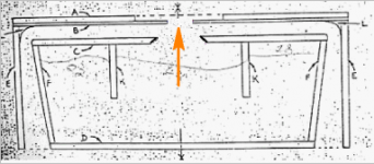
The Holliman box does not have any obvious labium, unless the edges of hole B and hole C are considered the labium, and I'm not sure how effective they would be at this task - the Holiman box is not laid out like any embouchure hole, fipple or whistle hole I've seen. So I'm not sure how effective the Holliman box would actually be at whistling.
Moving on, another quote from here - http://www.phys.unsw.edu.au/jw/fluteacoustics.html
The air jet has its own natural frequency that depends on the speed and length of the jet. To oversimplify somewhat, the flute normally plays at the strongest bore resonance that is near the natural frequency of the jet.
The latter part of this quote suggests that the resonant chamber and/or pipe attached to the air reed is the dominant factor in the tone produced. This is good news (to me) since it suggests that my Akabak simulation is mostly correct in characterizing all aspects of the Holliman box. In other words, even if there is a whistle effect, it's not going to magically play a 7 hz note due to whistle action.
On the other hand, the not so good news is that the speed of airflow will actually change the pitch. I didn't know about this since I don't play any wind instruments but all flute and recorder websites I've seen reference this fact. And it should be obvious to anyone that's played with a whistle. If you don't blow hard enough the whistle doesn't work at all, and as you progressively blow harder it starts making sound, getting louder and changing pitch. This can be controlled somewhat by a skilled player but not by a subwoofer box. This means that if there is significant whistle action in the Holliman box, rotating the volume knob on the amp will shift the pitch.
And finally, it took awhile but I finally found velocity values for air instruments. 20 - 60 m/s for a flute is typical and 35 m/s for a recorder. From these sites -
http://www.phys.unsw.edu.au/jw/fluteacoustics.html
http://iwk.mdw.ac.at/?page_id=95&sprache=2
So it seems like the Holliman box is operating in a typical whistle range but I'm still not convinced it's going to produce any real whistle action as opposed to just a whole lot of chuffing noise.
Last edited:
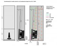
Graham Holliman encl. simulations
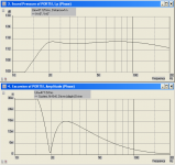
Hi there J: Once again, your efforts have added knowledge of the G.H. enclosure, Please notice the relationships between the 1w and 600w graphs posted for G.H. 15" enclosure. For comparison of the two curves, I over-laid the two curves in a screen trace with 100hz being equal for both curves. The 600w curve flattens the response and lowers the 20hz peak, shifts the peak slightly higher and reduces its slope, as well as extending the high roll off somewhat. This suggests that further tuning of an actual build may improve the response. regards, Michael
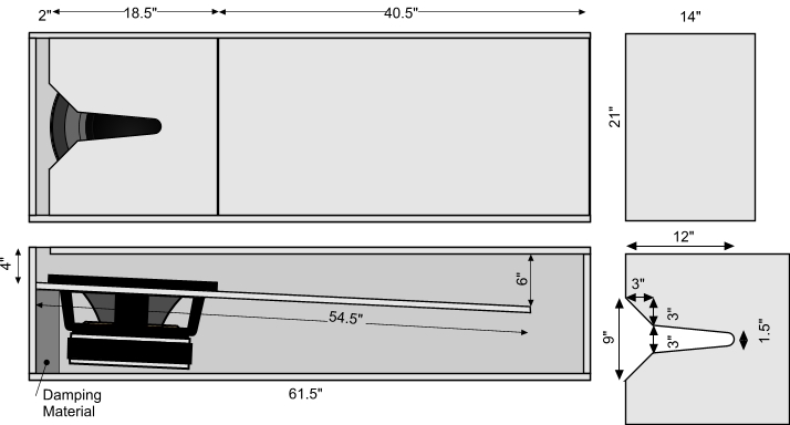
First, let me start by saying I expect people to check my work and make sure there are no mistakes. Please check to make sure I got cross sectional areas right (S1, S2, etc) and segment lengths correct (L12, L23, etc). Check my Hornresp inputs and my Akabak script. I'm going to look it over tomorrow to see if I can spot any errors but I think I captured the essence of this thing pretty well.
Ok, here we go...
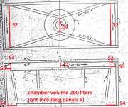
First up is a picture showing how I split it up into segments and calculated the compression chamber volume for Hornresp inputs.
An externally hosted image should be here but it was not working when we last tested it.
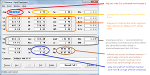
Next we have a picture of my Hornresp inputs. Everything is here except the details of hole c and the compression chamber. When you have to use Akabak I recommend starting with Hornresp first and importing that data into Akabak to continue, unless you are a masochist.
An externally hosted image should be here but it was not working when we last tested it.
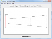
Starting with Hornresp gives a couple of important benefits, it generates the Akabak script for you and it allows you to view a schematic to make sure you aren't making stupid mistakes. Here's a picture of the Hornresp schematic (remember, this doesn't include hole C or the compression chamber but everything else is there).
An externally hosted image should be here but it was not working when we last tested it.
You can see I chose to use the Stereo Integrity HT 15 inch subwoofer Stereo Integrity | HT Subwoofers since it's a fair value, has 22.5 mm xmax and 600 wrms power rating so it should do what we need it to.
Next I exported the Hornresp data, which is as simple as going to the Input screen, selecting File - Export - Akabak script and then I placed that file into the Akabak script folder.
Then I opened the file in Akabak and continued the script by adding the details of hole C and the compression chamber. Hole C is a waveguide consisting of S5, S6 and L56. The compression chamber is an enclosure with a volume of 200.4 liters and a length of 1m.
(I will put the Akabak script in the next post.)
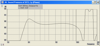
Then I ran a few simulations starting with frequency response at 1w.
An externally hosted image should be here but it was not working when we last tested it.
Not quite 7 hz. And clearly either the driver or the box dimensions need to change for smooth response down near tuning but that's not too important right now. Let's continue.
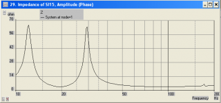
Here's the impedance.
An externally hosted image should be here but it was not working when we last tested it.
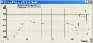
Response at 600 watts.
An externally hosted image should be here but it was not working when we last tested it.
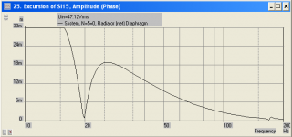
And driver excursion at 600 watts.
An externally hosted image should be here but it was not working when we last tested it.
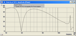
And at this point I was just itching to see the throat velocity (through the 3 inch diameter hole B). Here it is.
An externally hosted image should be here but it was not working when we last tested it.
Yup, that's approaching 60 m/s inside the passband. In fact this is unacceptable all the way through the passband with the exception of a small area right near tuning.
Unless I've made a terrible mistake somewhere this is not a viable design for modern drivers. Probably not for antique drivers either. Throat velocity like that is going to squeal like a little piggy even with both ends of hole B smoothed (as per the plans).
It's interesting to note that opening hole B up to a 5 inch diameter reduces throat velocity to about 20 m/s and doesn't change the response at all - it really doesn't change anything. But the point is that if it's built according to the plans you are going to see very high velocity through hole B. If I was going to build it I'd make hole B with a 6 inch diameter - that's the same size as hole C and it's as big as you can go without changing the design significantly.
But here's the interesting part. This next picture is the same driver in a similar sized ported box with the same 600w applied.
An externally hosted image should be here but it was not working when we last tested it.
Easier to build and much MUCH easier to simulate. IMO a much better solution overall.
Did I really just waste 8 hours on this? Yeah, I guess I did.
Hi there J: Once again, your efforts have added knowledge of the G.H. enclosure, Please notice the relationships between the 1w and 600w graphs posted for G.H. 15" enclosure. For comparison of the two curves, I over-laid the two curves in a screen trace with 100hz being equal for both curves. The 600w curve flattens the response and lowers the 20hz peak, shifts the peak slightly higher and reduces its slope, as well as extending the high roll off somewhat. This suggests that further tuning of an actual build may improve the response. regards, Michael
Hi freddi,
FYI:
b
PS: This is the easiest way to completely erase the annoying FR dip.
Can we see the sim?
I ask for two reasons:
1. Did you use the right dimensions? The dimensions on the diagram don't match the dimensions of the box he built. Which did you use?
2. I can't imagine the response is ideal with S2 so far down the line.
here's what I built with flooring plywood https://www.youtube.com/watch?v=UJTctkDPKpE
Please notice the relationships between the 1w and 600w graphs posted for G.H. 15" enclosure. For comparison of the two curves, I over-laid the two curves in a screen trace with 100hz being equal for both curves.
Before going to all that work did you notice the scale difference in the 1w and 600w graphs? There's 3db per division in the 1w graph and 6db per division in the 600w. Maybe I should have noted that.
The 600w curve flattens the response and lowers the 20hz peak, shifts the peak slightly higher and reduces its slope, as well as extending the high roll off somewhat.
No it doesn't, see note above about scaling. Even if it did any of these things that would not be a benefit. You don't want a box that changes response with power level.
I'm going to reload all the pics from the previous post directly to the forum since it seems my hosting service is a bit flaky and sometimes doesn't seem to want to load the pics. After all that work I'd hate to see the pics become unloadable or lost completely.
Attachments
-
 comparison.PNG37.5 KB · Views: 75
 -
 throat velocity.PNG19.9 KB · Views: 63
 -
 excursion 600w.PNG19.2 KB · Views: 84
 -
 600w.PNG19.2 KB · Views: 82
 -
 z.PNG18.8 KB · Views: 211
 -
 1w.PNG19.4 KB · Views: 216
 -
 holliman pic 2.png36.4 KB · Views: 224
 -
 holliman pic 1.png63.3 KB · Views: 228
 -
 holliman pic 3.png359.2 KB · Views: 234
I noticed a small error in my Akabak script. L56 is listed as:
L56 = 1e-2; |Compression chamber entry/exit
which is 1 cm. It should actually be:
L56 = 2.54e-2; |Compression chamber entry/exit
which is 1 inch, based on the 1 inch material thickness of panel C as per the plans.
The difference is incredibly small but in the interest of accuracy I thought I'd mention it in case anyone wanted to use my script.
Last edited:
I did some unscientific experimenting today with my 8" Holliman speaker... I added mass to the driver cone, increased the opening in panel "B", decreased the opening in Panel "B", added additional wings to the "exit ports", tried smaller room, and many combinations of the above, etc... I am not able to get additional output below 25hz....
Charlie
Charlie
#20 Graphical anomaily
Hi there J: There is a graphical departure from the regular arrangement of graph divisions of 3db between 86db and 89db, such that Graph #20 may show the response different along the curve. I agree that it is undesirable to have a change in the response curve with changing voltage and most simulations I've seen (or done) do not vary much in this way.
...regards, Michael
Before going to all that work did you notice the scale difference in the 1w and 600w graphs? There's 3db per division in the 1w graph and 6db per division in the 600w. Maybe I should have noted that.
No it doesn't, see note above about scaling. Even if it did any of these things that would not be a benefit. You don't want a box that changes response with power level.
Hi there J: There is a graphical departure from the regular arrangement of graph divisions of 3db between 86db and 89db, such that Graph #20 may show the response different along the curve. I agree that it is undesirable to have a change in the response curve with changing voltage and most simulations I've seen (or done) do not vary much in this way.
...regards, Michael
There is a graphical departure from the regular arrangement of graph divisions of 3db between 86db and 89db...
That is weird, I didn't notice that. I guess I should have shown 80 - 95 db instead of 94. I'll have to look into that at a later date. Maybe Akabak doesn't like fractions in the scaling legend. I'll have to keep an eye on that in the future, thanks for pointing it out.
Last edited:
@ just a guy
Hi, i appreciate your sims etc on this & everybody else who is contibuting too.
What everyone seems to be missing though, is that GH stated that Panel B should be as Thin as possible & as Rigid as possible. As i mentioned earlier on in the thread, i have the original Wilmslow Audio GH design i bought from them back in the day. I just dug it out, & he recommends either Formica or Dural of about 1/8th inch = 3.175mm.
I also feel sure that the HiFi magazine that published his design, & written by him back then which i have somewhere, said an alternative to having Panel B all 1/8th inch, would be to make the B hole area out of the Thinest/Stiffest material you could, & bond etc this to Panel B. So for eg, this could be Aluminium/Steel etc 1mm thick by 5" x 5" with a 3" centered hole !
How much of a difference it "might" make by reducing the thickness as much as possible ? But i think it's worth simming/trying just to see
Hi, i appreciate your sims etc on this
& everybody else who is contibuting too. What everyone seems to be missing though, is that GH stated that Panel B should be as Thin as possible & as Rigid as possible. As i mentioned earlier on in the thread, i have the original Wilmslow Audio GH design i bought from them back in the day. I just dug it out, & he recommends either Formica or Dural of about 1/8th inch = 3.175mm.
I also feel sure that the HiFi magazine that published his design, & written by him back then which i have somewhere, said an alternative to having Panel B all 1/8th inch, would be to make the B hole area out of the Thinest/Stiffest material you could, & bond etc this to Panel B. So for eg, this could be Aluminium/Steel etc 1mm thick by 5" x 5" with a 3" centered hole !
How much of a difference it "might" make by reducing the thickness as much as possible ? But i think it's worth simming/trying just to see
Attachments
@ just a guy
What everyone seems to be missing though, is that GH stated that Panel B should be as Thin as possible & as Rigid as possible. As i mentioned earlier on in the thread, i have the original Wilmslow Audio GH design i bought from them back in the day. I just dug it out, & he recommends either Formica or Dural of about 1/8th inch = 3.175mm.
I didn't miss it. What I did miss was the smoothing (roundover) on both sides of hole B as per the plans but that would be a much more complicated sim to do and wouldn't make much difference.
Here's the line in the Akabak script describing the length of hole B.
Lpt = 0.32e-2; |Throat adaptor length (m)
I admit I could have been more accurate and used 0.3175 cm instead of 0.32 cm but I didn't think rounding up would hurt since the difference is 0.0025 cm.
You can also see this in the picture of the Hornresp script. Look at "Lpt" (in the blue circle). To the right (in blue text) I even state it's 1/8 inch.
An externally hosted image should be here but it was not working when we last tested it.
Last edited:
I did some unscientific experimenting today with my 8" Holliman speaker... I added mass to the driver cone, increased the opening in panel "B", decreased the opening in Panel "B", added additional wings to the "exit ports", tried smaller room, and many combinations of the above, etc... I am not able to get additional output below 25hz....
Charlie
The 8" version I guess are not supposed to go down to 7 Hz. So if you have measured a flat response down to 25 Hz, this might still be better than what you would get from a similar simulation as Just A Guy has done for the 15" version.
How big is the chamber for your 8" version?
Would be really nice to see a similar sim of your build, and your measurements to compare.
Wether it is a "wistle" or "chuffing" noise might not matter way down below, if it is not producing artefacts further up in the freq spectrum. Even having say 50% distortion at 10 Hz, might be a lot better than not having any sound at all!
I'm though a little sceptic on what material actually have much sound below 20 Hz ....... I'v done some experiments with my own sub to find out how deep you actually have to go, and I didn´t find many recordings with any sound below 25 Hz. Does any of you guys have a list of material which actually have sound that deep. And do you also have some software which can show it ..... would be cool.
On the other hand I have once or twice heard a sub, which had the ability to produce really really deep sound, and the feeling was more that the room was breathing (for lack of better words), than real sound ..... but super impressive ..... it added the feel of space and room ..... would love to have this at home
ATTENTION "RESONANT CONSPIRACY THEORISTS"@ just a guy
Hi, i appreciate your sims etc on this
What everyone seems to be missing though, is that GH stated that Panel B should be as Thin as possible & as Rigid as possible. As i mentioned earlier on in the thread, i have the original Wilmslow Audio GH design i bought from them back in the day. I just dug it out, & he recommends either Formica or Dural of about 1/8th inch = 3.175mm.
I also feel sure that the HiFi magazine that published his design, & written by him back then which i have somewhere, said an alternative to having Panel B all 1/8th inch, would be to make the B hole area out of the Thinest/Stiffest material you could, & bond etc this to Panel B. So for eg, this could be Aluminium/Steel etc 1mm thick by 5" x 5" with a 3" centered hole !
How much of a difference it "might" make by reducing the thickness as much as possible ? But i think it's worth simming/trying just to see
Ummm, looks like we have another suspicious suspect to resonate about, tympanic membranes.
BTW, I've looked at the spectrum of a lot a recordings to find low bass notes, hear a lot of organ music (see my thread about the Halloween costume concerts in Toronto), and love great bass... but a speaker system that went down to 25 Hz nicely would leave just about nothing out even for keen fans of bass (I'd really like to say 32 Hz but that would start a flame war). Yes, there are people who love to listen to earthquakes and disaster movies but let's not confuse fun theatrical effects with music.
Ben
Last edited:
- Home
- Loudspeakers
- Subwoofers
- Graham Holliman Velocity Coupled Infra Bass Speaker?