Hi Upstate NY low life,
Post #242: "The only part that confuses me..."
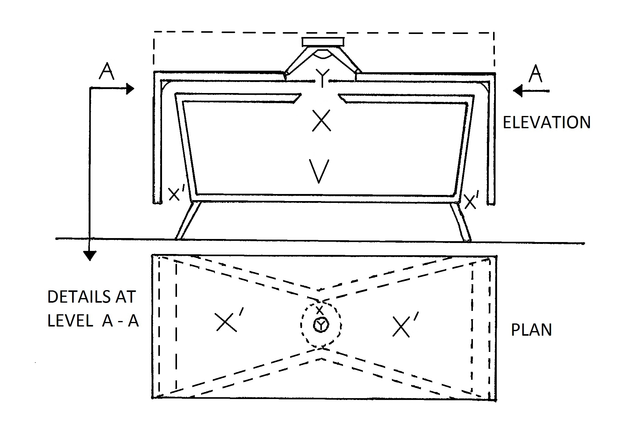
What you are calling the "bowtie wings" is the first section of the horn that is part of this design.
The driver energizes a way undersized bifurcated (split?) horn that is composed of the horizontal sections (the bowtie), and of the vertical sections (left and right of the box "V"), all horn sections are marked "X' ". The driver is coupled to the horn through a throat chamber with a throat opening called "Y". At the throat a Helmholtz resonator is also coupled to the begining of the horn; the resonator consists of volume "V" and opening "X". The drawing indicates that the back of the driver is left open to the room.
I doubt very much that there is any difference in principle between the box in the patent drawing, and the RobWells drawing in Post #162; just a different layout, and obviously the RobWells enclosure is designed for a different (modern?) driver.
From the general description above you should be able to develop an AkAbak model for this design. You could start by entering the horn data into Hornresp, and exporting the data as an AkAbak script file. Then you could add the resonator box to the AkAbak script, as well as respective electronic low cut, and high cut filters. That would give you a model with which you could evaluate the operation of the Graham Holliman enclosure with modern drivers.
Regards,
Post #242: "The only part that confuses me..."
What you are calling the "bowtie wings" is the first section of the horn that is part of this design.
The driver energizes a way undersized bifurcated (split?) horn that is composed of the horizontal sections (the bowtie), and of the vertical sections (left and right of the box "V"), all horn sections are marked "X' ". The driver is coupled to the horn through a throat chamber with a throat opening called "Y". At the throat a Helmholtz resonator is also coupled to the begining of the horn; the resonator consists of volume "V" and opening "X". The drawing indicates that the back of the driver is left open to the room.
I doubt very much that there is any difference in principle between the box in the patent drawing, and the RobWells drawing in Post #162; just a different layout, and obviously the RobWells enclosure is designed for a different (modern?) driver.
From the general description above you should be able to develop an AkAbak model for this design. You could start by entering the horn data into Hornresp, and exporting the data as an AkAbak script file. Then you could add the resonator box to the AkAbak script, as well as respective electronic low cut, and high cut filters. That would give you a model with which you could evaluate the operation of the Graham Holliman enclosure with modern drivers.
Regards,
Last edited:
Okay, I think I see now. So the dotted lines are a widening horn channel that connects the top of the resonator to the top plate. So in reality there is no space there as it is shown in the top diagram?
And acutally, in response to "way undersized," I believe Holliman stated that it is not acting as a horn, but rather a slowly tapering port? I know there is some precise description of the cruciality of the angle of the port and that it should be as long and slow as possible. I think I understand it. Yeah, it's just a long, lightly tapered bass port designed to lower the tuning frequency of the entire unit as the frequency of the resonator itself is rather high. Perhaps tapered to reduce port noise? Which doesn't seem possible as docile as the driver action is... maybe to act as a hybrid between a port and a horn, acting mainly as a port but with slight horn-y") attributes. Actually, wait a minute. Holliman claims the design to be effective over a wide range of frequencies (though 8-25 Hz doesn't sound wide, it's in fact over 3 octaves), and actually becoming more efficient as the frequency decreases (similar to a rotary?), and I know the unique port (not horn) has everything to do with this ability.
attributes. Actually, wait a minute. Holliman claims the design to be effective over a wide range of frequencies (though 8-25 Hz doesn't sound wide, it's in fact over 3 octaves), and actually becoming more efficient as the frequency decreases (similar to a rotary?), and I know the unique port (not horn) has everything to do with this ability.
I made that diagram BTW, because the first one was so rough. Now it will be easier for people in the future trying to find it. Share the power that is knowledge.
File:Graham Holliman Velocity-Coupled Infra Bass speaker design.jpg - Wikipedia, the free encyclopedia
And acutally, in response to "way undersized," I believe Holliman stated that it is not acting as a horn, but rather a slowly tapering port? I know there is some precise description of the cruciality of the angle of the port and that it should be as long and slow as possible. I think I understand it. Yeah, it's just a long, lightly tapered bass port designed to lower the tuning frequency of the entire unit as the frequency of the resonator itself is rather high. Perhaps tapered to reduce port noise? Which doesn't seem possible as docile as the driver action is... maybe to act as a hybrid between a port and a horn, acting mainly as a port but with slight horn-y
attributes. Actually, wait a minute. Holliman claims the design to be effective over a wide range of frequencies (though 8-25 Hz doesn't sound wide, it's in fact over 3 octaves), and actually becoming more efficient as the frequency decreases (similar to a rotary?), and I know the unique port (not horn) has everything to do with this ability. I made that diagram BTW, because the first one was so rough. Now it will be easier for people in the future trying to find it. Share the power that is knowledge.
File:Graham Holliman Velocity-Coupled Infra Bass speaker design.jpg - Wikipedia, the free encyclopedia
Last edited:
Holliman claims the design to be effective over a wide range of frequencies (though 8-25 Hz doesn't sound wide, it's in fact over 3 octaves).........
You're apparently thinking harmonic structure. Octave spreads are a 2:1 ratio [exponential], so this is only ~10*log10[25/8]/3.01 = ~1.644 octaves. A 3 octave spread would be 8-16-32-64 Hz [rounded off].
GM
YWhoops, I'm sorry, you're right. I knew that it just slipped my mind. However, it still is as much as a two+ octave range as I believe it was actually stated to start at 6 Hz. I've noticed that on this and other "infrasonic patents" different frequencies are given throughout. And, in fact, the response can go well above 25 Hz, it's just not recommended because it is not suitable for it and a traditional subwoofer should start at 25 Hz. I have an idea it would sound terrible at audible bass frequencies, anyway. I'm excited about building this. I'd like it to be the largest one suggested, to go for good response down to 5 Hz. Then I could brag that I've got flat response all the way from 5 to 25 (Hz to kHz)
I don't think so.
And the build should be pretty easy. But I do not have specific instructions for the 18 inch, original one. I should use MDF, even marine grade plywood has plywood characteristics I don't like. And one layer of 3/4 should actually be fine, for this thing is so docile in a way that it shouldn't matter. I find that mid bass frequencies are actually the hardest as far as enclosure resonance, while sub bass frequencies are harshest for enclosure flex, which is essentially just slower resonance. I guess it's sort of a phenomenon that ultra low frequencies stop having this problem. I'm sure it's only because they rely on low power and high efficiency, because no driver is meant to put them out at high power.
The South African also has some chicken scratch diagrams showing some are shapes I don't quite understand. He also has "standing wave control inserts" that must be intended for the resonating chamber which I don't understand. But mainly, take a look at this image:
Nevermind LOL. It's just the feet. Their the most intricate part there is, they're supposed to have a nice curve to them. Screw that.
Everything else being said, and finally feeling like I've got a full grip on this and am over the surprises (like the feet, fearing that diagram was an inside-y part was meant to have a perfect curve that unless done right would muck it all right up :/), what do you guys make of the varying sizes and their relationship between one another for the different driver/box sizes? I maintain that they simply cannot all perform similarly in the same ULF range, and I would like to go full tilt and extrapolate what the 18 inch size should be (and use double thickness-1.5", I won't stop till it kills me) but I am not sure I should venture out when the design seems to necessitate some amount of precision. The South African, as well as a story by another guy who had auditioned one that by description sounded like it was a 10 or a 12, both testified to the nauseating effects of the apparatus, but I don't want to take any chance that I build it and it's a flop. Being aware of phasing issues and having several unique spaces to try it in (though none are well sealed, I should be able get some desired result even if I extrapolate for an 18. As far as the woofer, I already have the aforementioned Peavy 18 in mind, which if proves to be insufficient, is only a few hundred bucks so it's not a huge deal, and will be more than useful for other things. Not probably considering the exotic Focal 18. Any driver recomendations by you guys would be appreciated. If you know of a superb 15 I'd be steered to go with that design.
And the build should be pretty easy. But I do not have specific instructions for the 18 inch, original one. I should use MDF, even marine grade plywood has plywood characteristics I don't like. And one layer of 3/4 should actually be fine, for this thing is so docile in a way that it shouldn't matter. I find that mid bass frequencies are actually the hardest as far as enclosure resonance, while sub bass frequencies are harshest for enclosure flex, which is essentially just slower resonance. I guess it's sort of a phenomenon that ultra low frequencies stop having this problem. I'm sure it's only because they rely on low power and high efficiency, because no driver is meant to put them out at high power.
The South African also has some chicken scratch diagrams showing some are shapes I don't quite understand. He also has "standing wave control inserts" that must be intended for the resonating chamber which I don't understand. But mainly, take a look at this image:
Nevermind LOL. It's just the feet. Their the most intricate part there is, they're supposed to have a nice curve to them. Screw that.
Everything else being said, and finally feeling like I've got a full grip on this and am over the surprises (like the feet, fearing that diagram was an inside-y part was meant to have a perfect curve that unless done right would muck it all right up :/), what do you guys make of the varying sizes and their relationship between one another for the different driver/box sizes? I maintain that they simply cannot all perform similarly in the same ULF range, and I would like to go full tilt and extrapolate what the 18 inch size should be (and use double thickness-1.5", I won't stop till it kills me
) but I am not sure I should venture out when the design seems to necessitate some amount of precision. The South African, as well as a story by another guy who had auditioned one that by description sounded like it was a 10 or a 12, both testified to the nauseating effects of the apparatus, but I don't want to take any chance that I build it and it's a flop. Being aware of phasing issues and having several unique spaces to try it in (though none are well sealed, I should be able get some desired result even if I extrapolate for an 18. As far as the woofer, I already have the aforementioned Peavy 18 in mind, which if proves to be insufficient, is only a few hundred bucks so it's not a huge deal, and will be more than useful for other things. Not probably considering the exotic Focal 18. Any driver recomendations by you guys would be appreciated. If you know of a superb 15 I'd be steered to go with that design.
Last edited:
I am undergoing final calculations, am thouroughly past misunderstandings and surprises, have figured the rough total box volume of the 15 to be about nine cubic feet, which isn't as big as I thought. When I heard the one guys story read "large box about 5 feet long and maybe 2 1/2 feet wide" I thought it was huge.
Pretty simple with just this table and this diagram:
All sizes | Graham Holliman instructions | Flickr - Photo Sharing!
^^
See how much better that is than the prehistoric image hosters you were using before that are now all gone?
Geez, it looks too easy!
Only, where and what is measurement "M," which is supposed to be 6.5 inches on the 15 and 4 on the 10, is that the total distance between the inside of C and the outside of A? That should not be necessary to specify as the thickness of the other pieces defines that...but that's what I'm guessing because the only place I think I see it is written sideways and being intesected by a line in the small cross section diagram...
Another thing is it doesn't say at what points along piece C to put standing wave inserts K, although it looks like there is a 22 scribled in there, this can't be possible; however, I do belive the South African said their placement is not critical, only that they are there. Although it seems like for spl a standing wave would be desired because it would give it a peak, which at 5-20 Hz could be interesting...
Also note how B is shown thinner than A in the diagram meaning that really, since they're doubled up, there is no need for B to be that thick. Actually the part of B that is directly under the driver is the part where Holliman specified absolutely no flex is acceptable and should be made of mica or some odd metal/rock or something. I wonder how much of an effect thickenss would have, the two mouths are not acting as ports to any critical degree, however the larger one into the resonating tub is cut at 45 degrees as if precision matters. If I were to double up walls it would be the outside walls I guess, I could double up F and C and slowly taper them toward the mouth and compensate by adding 1.5 inches to the outer dimensions (I'll already have to adjust this for using 3/4 MDF vs 1 inch marine plywood, who knows how this will affect it, and.... then agian I truly don't believe doubling should be necessary becuase of it's efficiency which is the whole point to it. Oh, which leads to another question, should I just use (the very expensive) 1 inch marine plywood? Per equal thickness, which is stiffer/better/less resonant, HQ plywood or average MDF? What about High Density Fiberboard? And acutally it's hard to find anything in one inch. One time I asked for one inch MDF and they looked at me like I was crazy. They actually looked it up and found out they could order it but it was phenominally expensive. God to answer all my questions I'll have to build about 10 of 'em!
Holliman (actually when I say Holliman I'm not sure what is original and what is the South African saying it) stressed the importance of the slow curve of the long port, which makes me think the diagram shows the battens being much too sharp in comparison to the final taper which is much less, which could make it like a horn. Perhaps this is not to scale.
^^
That is largely me talking to my self as a reference, my main questions for you guys are:
a). A good driver and b). what material to use
With the super high efficiency, if I were to go with an extrapolated 18 inch version, I could probably use my garbage Pyle 18, as this was intended to be operated in only the two digits of watts range. I honestly think the driver itself should amount to jack nothing in the performance of this instrument.
Also, I do conclude that this is all legitimate and that the South African't 22 page PDF is not hearsay and this not a Jonny one note boombox and those grainy diagrams are clearly scans of the original and the whole introduction sounds English, as well as the instructions for the decorative feet
Last edited:
Don't you guys think it would be better if the inside part (tub shaped resonator) would be better off rectangular and let the outside walls angle out, resulting in the entire unit having a trapezoid shape instead of the inside part? Also, and I should have known this, the South African figured the standing wave control insterts to be spaced equidistantly, 1/4 from the ends and 1/2 from each other. But what's confusing is that you can see what looks like 22, 64, then 28 written between the inserts.
Confirmation etc
Re - Graham Holliman
I remember reading about the Graham Holliman Infrabass speaker in one of the HiFi mags in the early eighties, & being fascinated with it. On several of my infrequent visits to the National Archives in Yorkshire to look up various Audio/Electronic data/info et cin numerous books/magazines etc etc, i discovered that ALL copies of Anything Graham Holliman related were missing, & no suitable explanation as to why ?
Round about 1981/2 i was fortunate to actually see what i "believe" was a Graham Holliman designed full range system in Island records studios disc cutting room in London. Myself, and a friend of mine who knew someone at Island, were being shown around. My friend mentioned to the engineer in the DCR, that i was into HiFi/electronics etc etc, & when i asked what make the floor standing speakers with no name on them were, that's when i found out a "bit" more. He said they were a custom/special Infrasonic one off design, designed/built to go down lower than anything else that was available. Unfortunately i didn't get to hear them as he was busy calibrating some circuit boards. I asked if he would give me the guys details so i could contact him to find out more etc, but was told the guy worked, or did some work, for the government/military so it was out of the question. Of course it "might" have been "another" Infrasonic speaker design ? But quite a coincidence if it was, especially around that time !
Re - Wilmslow Audio
I can confirm that having purchased the original Graham Holliman plans from Wilmslow Audio in the 1980's, which i still have & managed to find to compare against the PDF that Ryan Reynolds from South Africa made. He did a Very good job at scanning it, & as stated it Really is the real deal. Yes those grainy hand drawn etc diagrams & photos are as found in the original Wilmslow Audio booklet plans. This came as a fawn coloured booklet complete with an unfold & open out section that contained the actual drawings etc at the inside back page. He nicely tidied up the original layout, but missed out the following short passage, which i've included for completeness.
Right before, Final Assembly, should be this paragraph.
I'll try & maybe take some photos of it & upload them at some point.
Re - Richard Allan
I purchased several different models from Richard Allan over a number of years, including 8" 12" & 15" drivers, though not the Atlas range. I still have/use the 8" bass/mid ones in a pair of 3 way floorstanders. The 2 pairs of high effeciency 15" & 12" drivers were loaded seperately into reflexed cabs for bass/mid duties along with horn tweeters, all crossed over passively. They were originally built & used for disco/PA work, & later for some time used at home ! before i sold them to a local band to use as their PA. The point of my relating this, is to try & convey just how versatile/beefy & high quality, that RA drivers were/are ! Sadly RA were taken over some years ago & only seemed to last a few years more before going out of business
*
It's nice to hear that people are still interested in the GH concept/design after all these years, & always wondered why it wasn't developed commercially by some company ? If GH could be contacted & persuaded to contribute as much further info as possible about the whole thing, that would be Most welcome.
Re - Graham Holliman
I remember reading about the Graham Holliman Infrabass speaker in one of the HiFi mags in the early eighties, & being fascinated with it. On several of my infrequent visits to the National Archives in Yorkshire to look up various Audio/Electronic data/info et cin numerous books/magazines etc etc, i discovered that ALL copies of Anything Graham Holliman related were missing, & no suitable explanation as to why ?
Round about 1981/2 i was fortunate to actually see what i "believe" was a Graham Holliman designed full range system in Island records studios disc cutting room in London. Myself, and a friend of mine who knew someone at Island, were being shown around. My friend mentioned to the engineer in the DCR, that i was into HiFi/electronics etc etc, & when i asked what make the floor standing speakers with no name on them were, that's when i found out a "bit" more. He said they were a custom/special Infrasonic one off design, designed/built to go down lower than anything else that was available. Unfortunately i didn't get to hear them as he was busy calibrating some circuit boards. I asked if he would give me the guys details so i could contact him to find out more etc, but was told the guy worked, or did some work, for the government/military so it was out of the question. Of course it "might" have been "another" Infrasonic speaker design ? But quite a coincidence if it was, especially around that time !
Re - Wilmslow Audio
I can confirm that having purchased the original Graham Holliman plans from Wilmslow Audio in the 1980's, which i still have & managed to find to compare against the PDF that Ryan Reynolds from South Africa made. He did a Very good job at scanning it
, & as stated it Really is the real deal. Yes those grainy hand drawn etc diagrams & photos are as found in the original Wilmslow Audio booklet plans. This came as a fawn coloured booklet complete with an unfold & open out section that contained the actual drawings etc at the inside back page. He nicely tidied up the original layout, but missed out the following short passage, which i've included for completeness.Right before, Final Assembly, should be this paragraph.
"It is advisable to proceed in a particular order when dealing with final assembly, otherwise one may find that some pieces cannot be fitted due to others already in place, being in the way"
I'll try & maybe take some photos of it & upload them at some point.
Re - Richard Allan
I purchased several different models from Richard Allan over a number of years, including 8" 12" & 15" drivers, though not the Atlas range. I still have/use the 8" bass/mid ones in a pair of 3 way floorstanders. The 2 pairs of high effeciency 15" & 12" drivers were loaded seperately into reflexed cabs for bass/mid duties along with horn tweeters, all crossed over passively. They were originally built & used for disco/PA work, & later for some time used at home ! before i sold them to a local band to use as their PA. The point of my relating this, is to try & convey just how versatile/beefy & high quality, that RA drivers were/are ! Sadly RA were taken over some years ago & only seemed to last a few years more before going out of business
*
It's nice to hear that people are still interested in the GH concept/design after all these years, & always wondered why it wasn't developed commercially by some company ? If GH could be contacted & persuaded to contribute as much further info as possible about the whole thing, that would be Most welcome.
Yeah, I wasn't expecting on being able to find anything like the Richard Allen driver, but like I inferred, I'll bet with 95% certainty that it doesn't matter.
One more thing I'm leery of with the Sou..Mr. Reynolds "experience the wave" success was that not only was he using a cheap driver, it was also only the 10 inch design, and he was using a cheap amp, and here's the big one, he wasn't using a crossover, so that "amazing infrasonic bass" he got was probably just decent sub bass, which Mr. Holliman did say it was capable of without much issue. Also, to add yet another thing, he built it out of mediocre quality chip board for lack of better supplies, which makes a lot of factors, that in what seems like such a sensitive design, should have ruined the intended result. And maybe it did. But, Mr. Holliman argued that the design was intended to minimize room factors, which is the opposite of what Reynolds claimed he experienced.
So one of two things happened here with one being the much more exciting possibility:
1. Reynolds was dealing with "normal" sub-bass and it's attributes and not being highly accustomed to good bass, was more than satisfied
2. Even with all the off hand nature of his design, Reynolds was still getting a good result, meaning that if done right the result could be simply spectacular.
Lets hope for number 2
Still my only question is, do you think it's a good idea to go with the extrapolated 18 inch design, as all the other sizes are proportional in a linear nature. Since I now see how it works, I understand how it works with all the sizes, unlike what I was saying before how the bigger box should be tuned lower, but it has larger mouths and ports, so it works just like any other enclosure. Either way it's going to take a lot of head scratching, patience, and MDF, so I might as well go big. And as far as the importance of doing things in the right order, I don't think either of these guys were big enclosure constructors.
Last edited:
Exactly.if you look at the Graham patent, That little hole in front of the driver is a low frequency whistle with a Helmholtz resonator "jug" across from it. It's really that simple.
So, would this be the "infrasonic whistle" that supossedly was some sort of sonic weapon being designed by the French Vladimir Gavreau? Or was that just a large organ pipe he patented, like that joker who patended his oversized cube?
The Sonic Weapon of Vladimir Gavreau | Journal of Borderland Research
That article is fantasical and unreliable. Explode and kill. Nazi propoganda. What horse *****
150 Hertz infrasound! Great! The one's that allegedly "worked" at actual infrasonic frequencies were just a gigantic foghorn or a 75' x 6' organ pipe.
And who cares if that's "all it is." It's not magic, guys, it has to be something. So it's a whistle firing over a resonator. Sounds good. You're making it sound like it's "no good" becuase you can see what it is and understand it, as if it would better if it was a mystery, which is understandable to a degree.
The Sonic Weapon of Vladimir Gavreau | Journal of Borderland Research
That article is fantasical and unreliable. Explode and kill. Nazi propoganda. What horse *****
The infrasonic foghorns could produce a frightening two kilowatts of infrasonic energy, at a pitch of one hundred fifty cycles per second.
150 Hertz infrasound! Great! The one's that allegedly "worked" at actual infrasonic frequencies were just a gigantic foghorn or a 75' x 6' organ pipe.
And who cares if that's "all it is." It's not magic, guys, it has to be something. So it's a whistle firing over a resonator. Sounds good. You're making it sound like it's "no good" becuase you can see what it is and understand it, as if it would better if it was a mystery, which is understandable to a degree.
Last edited:
What do you guys see as the best building material? I really think the popularity of MDF is just a convenience thing because it's cheap and easy to work with and is satisfactory, though clearly still far from the best. What about hardboard, also known as high density fiberboard. It is much heavier and stiffer. I have noticed that even a medium sized braced enclosure of one layer of 3/4 MDF still flexed if you pounded it with your fist. Internal bracing on the G.H. is one of my last considerations. I really don't want to go through the hassle of adjusted dimensions due to doubling up the entire thing as well as the significant cost and weight increase this will have. However, the years of enjoyment and proper functionality gotten out of a quality product heavily outweighs the initial cost. I also find over building to be satisfying. If it's heavy you assume it's good. And there's nothing wrong with a solid base. "Are those heavy?" "yeah." "Then they're expensive, put em back."
Last edited:
Infrasonics
A very interesting post. I have been listening to
very low bass for years with a rotary subwoofer.
Will reproduce bass to below 1 hz and has no
trouble of being overdriven. Transients are frightening and distortion is very low. Many
Blueray movies have content to below 10 hz and
some much lower. Can be adjusted for different
size rooms and is very efficient (matches the impedance of the air). The entire bass range should
be in proportion to this infrasound for realism.
Attachments
And who cares if that's "all it is." It's not magic, guys, it has to be something. So it's a whistle firing over a resonator. Sounds good. You're making it sound like it's "no good" becuase you can see what it is and understand it, as if it would better if it was a mystery, which is understandable to a degree.
Seems obvious enough to me. I wonder what the group delay looks like?

Oh, and mind your language.
Okay, one critical thing that is absolutely not given in the instructions is the orientation of the battens. I am assuming they are the "tall way" if you know what I mean. It's a terminally critical matter because it defines the entire area of the horizontal part of the port. lol this is a "folded port" enclosure
The delay is that it's 180 degrees out of phase and needs to be hooked up backwards.
The delay is that it's 180 degrees out of phase and needs to be hooked up backwards.
Last edited:
upstate,
When i say " that's all it is" i'm not condescending, i'm just saying its simple.
group delay and phase delay are two different things, similar but different.
ref: Phase Delay and Group Delay
When i say " that's all it is" i'm not condescending, i'm just saying its simple.
group delay and phase delay are two different things, similar but different.
ref: Phase Delay and Group Delay
Richard Allen atlas T/S Specs +
I was going to dig out my RA leaflets with the specs & post them, but i found a thread on here with them
http://www.diyaudio.com/forums/multi-way/33249-richard-allan-speakers-t-s-parameters-attached.html
Hope it helps
I was going to dig out my RA leaflets with the specs & post them, but i found a thread on here with them
http://www.diyaudio.com/forums/multi-way/33249-richard-allan-speakers-t-s-parameters-attached.html
Hope it helps
- Home
- Loudspeakers
- Subwoofers
- Graham Holliman Velocity Coupled Infra Bass Speaker?