Dr.EM said:
Is it normal practice to have the tuning frequency at the drivers Fs? What would the F3 be roughly, somewhere below the tuning frequency i'd imagine? Strong response into the low 20's is quite important if possible (even if that is only "in room").
A lot of frequency response graphs of TL designs show quite severe looking ripples above the tuning frequency (starting at 3 times that freq?). I'd need a flat response up past my crossover frequency to ensure a good crossover; how can I ensure I don't get the ripples?
Hi,
Fs is the starting point for the calculations. It is possible to go a bit lower, but you lose efficiency. Lower but less output. The idea is to reinforce that area to increase output.
The model that I gave above will have an impressive amount of bass, and add to that room gain.
Depending on your crossover freq., ripple may or may not be a factor. The reason for moving the driver away from the line start is to cancel some of the ripple. Martin King recommends 1/5 driver offset as the best compromise. Stuffing will further reduce ripple.
MJL21193 said:Martin King recommends 1/5 driver offset as the best compromise. Stuffing will further reduce ripple.
It is more complex than that, as it depends on the line's taper. Here is a snapshot from Martin's Alignment Tables.
from ~ 2/5 to ~1/3 for the tapers in the document.
dave
Attachments
In Martin King's own words:
"Table 4 contains the maximum recommended driver offset positions. At these
driver positions, it is possible to almost completely suppress the second mode (threequarter
wavelength) and every other quarter wavelength mode (seven-quarter
wavelength, eleven-quarter wavelength …) above this point. One consequence of
offsetting the driver is a reduction in the excitation applied to the fundamental quarter
wavelength mode, the tuning frequency of the line, and some reduction in bass
extension. By placing the driver someplace between the closed end (î = 0) and the
maximum offset ratio shown in Table 4, a compromise response results. A commonly
found recommendation for the driver offset ratio î is 0.2."
With he MathCad worksheets, driver offset can be fine-tuned to best possible position. If you do not have the worksheets, the 1/5 offset will be the best compromise.
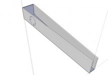
Ok, trying to draw this design. I'm finding it difficult to lay it out as a folded design. How do you calculate it, as in the folds? Say I want a height defined as 770mm, how can I work out the folds and thus the depth of the box? We know the internal width is 12" for this design.
Drawing it as a straight model is quite easy as you can see in my first attempt at using Sketchup . Is that program ideal for drawing speaker designs, only really need 2D I think. When Planet 10 drew a box for me it looked really neat as a 2D with dimensions, what was used?
Drawing it as a straight model is quite easy as you can see in my first attempt at using Sketchup
. Is that program ideal for drawing speaker designs, only really need 2D I think. When Planet 10 drew a box for me it looked really neat as a 2D with dimensions, what was used?Attachments
Dr.EM said:how can I work out the folds and thus the depth of the box? We know the internal width is 12" for this design.
I'm too lazy (or busy) to learn sketch up - one of these days.
Line length is down the centre of the space, as illustrated
in my (MS paint) drawing (red line).
I have had more luck with a scale drawing on paper to get the correct dimensions.
Attachments
Vectorworks I guess... (Having seen some of his drawings)Dr.EM said:When Planet 10 drew a box for me it looked really neat as a 2D with dimensions, what was used?
Paul
bibster said:Vectorworks I guess... (Having seen some of his drawings)
Correct. Most 2 D is done in Vectorworks (sometimes Illustrator plays a role)
DWGs or DXFs of basic geometry are exported & then imported into SketchUp. A snapshot taken of the visualization is taken thru photoshop back into Vectorworks, that is printed to pdf (and sometimes taken thru Acrobat for optimization)
dave
Low Q drivers in a TL...
Onur Ilkuror has figured out how to use low Q drivers in a TL. You can have a look at his designs on his site. They work well but size is increased with this kind of driver.
http://www.yildiz.edu.tr/~ilkorur/
Onur Ilkuror has figured out how to use low Q drivers in a TL. You can have a look at his designs on his site. They work well but size is increased with this kind of driver.
http://www.yildiz.edu.tr/~ilkorur/
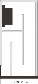
Here's my take, I like to keep the line simple, the taper is created by narrowing the depth of each turn. You can scale the height to get the right length & the depth to get the right cross-sectional area.
Not sure how to get the driver positioned at the 1/5th mark.
Andrew.
Not sure how to get the driver positioned at the 1/5th mark.
Andrew.
Attachments
Ap said:Not sure how to get the driver positioned at the 1/5th mark.
Mount it on what is currently the back of the box. That will get it close.
dave
Ap said:
Not sure how to get the driver positioned at the 1/5th mark.
Greets!
Measure the internal long side path-length, ditto the short inside one, then L = SQRT(long*short), zdriver = L*0.2, so wherever this length terminates along the centerline of the pipe from the closed end is the centerline of the driver cutout.
GM
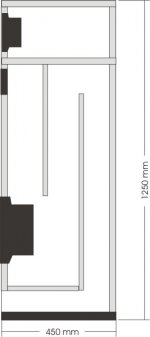
Ok, heres another design, this is 3 way with mid mounted above tweeter (due to height), however If you use a dome mid you can do without the top chamber & mount it below tweeter.
Having the woofer low to the floor helps reduce the floor reflection & also having the exit at the floor will give it some boundary re-inforcement.
I'm guessing line length at about 2.8m which is 30hz. (1/4 wave)
Andrew.
Having the woofer low to the floor helps reduce the floor reflection & also having the exit at the floor will give it some boundary re-inforcement.
I'm guessing line length at about 2.8m which is 30hz. (1/4 wave)
Andrew.
Attachments
Found this on the web after some browsing, has pdfs with specific dimensions. Enjoy.
http://www.aos-lautsprecher.de/english/studio100tlE.html
http://www.aos-lautsprecher.de/english/studio100tlE.html
Re: hi
If you take a look at this thread, especially the second page, you will see that Martin's sims show that for the bottom two octaves, the action of the Transmission Line and the Bass Reflex are the same. This is for a Transmission Line and Bass Reflex of identical volume.
he F3, cutoff slope, impedance graph,etc are all the same for the bottom two octaves. The only difference is the resonances higher up the scale for the Transmission Line, which is why they are stuffed so much.
Amit_112dB said:
Plus i would like to share what Dr. Martin J Kings told me on weekend -
Bass reflex enclosures and TL are more similar then most people admit. I think that the reason some people like a TL better then a bass reflex is for two reasons.
1. The fiber damping removes any ring and boomy response. It makes the transition into the 24 db/octave rolloff more gradual so a resonant note at the tuning frequency does not occur. The fiber also helps kill any higher order resonances in the enclosure which in general leads to a cleaner mid bass response.
2. Tuning of the enclosure is not as critical. Basically a bass reflex box can be easily mistuned, the port is a little too long or the box volume is slightly off. This can lead to either boomy bass or weak bass. A TL seems to be a little more forgiving of errors in the cabinet design and it can easily be adjusted by adding or removing some fiber stuffing.
If you take a look at this thread, especially the second page, you will see that Martin's sims show that for the bottom two octaves, the action of the Transmission Line and the Bass Reflex are the same. This is for a Transmission Line and Bass Reflex of identical volume.
he F3, cutoff slope, impedance graph,etc are all the same for the bottom two octaves. The only difference is the resonances higher up the scale for the Transmission Line, which is why they are stuffed so much.
Thanks for all the help, I may well buy the worksheets and play around myself.
That is interesting about comparing the BR to TL designs. In a BR this woofer has a pretty poor response with a -3db point at about 50Hz (bizzarely the 4" version has a lower F3 ). In a TL however the enclosure is tuned with the 31Hz resonance frequency which I assume gives a F3 below 30Hz?
I have a TL sub based on Morel HU-631's designed by people on this board. It produces some pretty low frequencies, much lower than my BR speakers (B&W DM602S3) I was using on thier own before. They are also in an enclosure much bigger than the BR would have been.
That is interesting about comparing the BR to TL designs. In a BR this woofer has a pretty poor response with a -3db point at about 50Hz (bizzarely the 4" version has a lower F3
). In a TL however the enclosure is tuned with the 31Hz resonance frequency which I assume gives a F3 below 30Hz?I have a TL sub based on Morel HU-631's designed by people on this board. It produces some pretty low frequencies, much lower than my BR speakers (B&W DM602S3) I was using on thier own before. They are also in an enclosure much bigger than the BR would have been.
Good idea. If you are going to keep building enclosures as you do, you're probably going to end up getting them anyway. Plus Martin is generous with his help using the sheets, and if you post a problem using them Martin or someone else skilled with them will fix you up with an answer lickety-split.Dr.EM said:Thanks for all the help, I may well buy the worksheets and play around myself.
Just as in a BR design, tuning the enclosure to a low frequency does not guarantee the F3 will be at that frequency. Depending on the speaker's Fs and Vas, you can actually be 6 or 8 dB down or more at the tuning frequency, in either the BR or TL.Dr.EM said:That is interesting about comparing the BR to TL designs. In a BR this woofer has a pretty poor response with a -3db point at about 50Hz (bizzarely the 4" version has a lower F3
Dr.EM said:I have a TL sub based on Morel HU-631's designed by people on this board. It produces some pretty low frequencies, much lower than my BR speakers (B&W DM602S3) I was using on thier own before. They are also in an enclosure much bigger than the BR would have been.
No question about it, for a given speaker in either TL or BR, bigger enclosure = more bass. The only issue is the quality of bass-if the enclosure is too large you'll have a lot of bass but also a lot of distortion and boom.
To my knowledge, the TL does not give a lower F3 or more bass than a comparably sized BR tuned to the same frequency, in fact it is usually the opposite. Now the Mass Loaded Transmission Line, (MLTL), which is sort of a combo TL and BR-that can give lower F3 than either the TL or BR.
Originally posted by MJL21193 Formula: So/Sd=p*c*Sd*Dz*Dr*Re/(Bl)^2
Sorry to revive this old thread! I am trying to calculate a TL for a different driver but am now stuck as I can't remember what p and c are in your equation! Can anyone remember
Don't worry, think I have figured it out, just use (1.21 kg/m3) and (342 m/sec) as in the demonstration equation, they are constants? Overall response doesn't look too healthy though. Is TL for M8a driver, expected a decent response but looks barely better than infinite baffle response . Got length at 83in, SO at 2.044 and SL at 0.681 to define a 3:1 taper. Check it out on the worksheets if you have them and see what you think, sure it should be "better".
. Got length at 83in, SO at 2.044 and SL at 0.681 to define a 3:1 taper. Check it out on the worksheets if you have them and see what you think, sure it should be "better".- Status
- This old topic is closed. If you want to reopen this topic, contact a moderator using the "Report Post" button.
- Home
- Loudspeakers
- Subwoofers
- Good for transmission line?