Those circuits are for common mode noise reduction. That applies to pro audio, if I'm not mistaken.
I've never seen a head unit with a source resistor to ground but some of the Kenwood head units had balanced outputs and both outputs would have had the same source/output resistance/impedance.
I've never seen a head unit with a source resistor to ground but some of the Kenwood head units had balanced outputs and both outputs would have had the same source/output resistance/impedance.
Brand names that did this sort of Balancing act to there car amps:
ADCOM< All amps ever made, no longer in production both RCA and Balanced line driver setup possible Built Mid to late 90's 5 pin DIN plug connections
ZAPCO < Many models over the years, some balanced line drive only requiring ZAPCO Balanced Line Driver module. < Local company to my area, just over the hill. Built currently on many models. Custom PS-2 computer like plug connection
Phoenix Gold ZPA 0.3 and 0.5 Amp series Audiophile grade car amplifiers again both RCA and balanced line drive capable using CAT-5 or 6 cabling. Used only on ZPA series but PG also built outboard line drivers to augment any stand alone system. You can find these on e-bay from time to time. Built mid to late 90's but not currently. Early models used PS-2 plug like connections but these had a issues of self disconnection (i.e. the plugs fell out of there sockets ) So the second version used CAT-5 and 6 plugs and cabling.
There were a few others over the years but I own two of the three listed above. I do have the modules on my bench for testing all of these amps since I work on them from time to time. I just have never installed them at this point. So I never have used the BLD setup before myself even though I own the stuff to do it with...Crazy eh?")
I have heard horror stories about bad setups using BLD's and having all sorts of unexplained noise issues due mostly to inexperience and poor installation HISS related noise floor issues but this can be caused by mis-adjusted gains in most cases
ADCOM< All amps ever made, no longer in production both RCA and Balanced line driver setup possible Built Mid to late 90's 5 pin DIN plug connections
ZAPCO < Many models over the years, some balanced line drive only requiring ZAPCO Balanced Line Driver module. < Local company to my area, just over the hill. Built currently on many models. Custom PS-2 computer like plug connection
Phoenix Gold ZPA 0.3 and 0.5 Amp series Audiophile grade car amplifiers again both RCA and balanced line drive capable using CAT-5 or 6 cabling. Used only on ZPA series but PG also built outboard line drivers to augment any stand alone system. You can find these on e-bay from time to time. Built mid to late 90's but not currently. Early models used PS-2 plug like connections but these had a issues of self disconnection (i.e. the plugs fell out of there sockets ) So the second version used CAT-5 and 6 plugs and cabling.
There were a few others over the years but I own two of the three listed above. I do have the modules on my bench for testing all of these amps since I work on them from time to time. I just have never installed them at this point. So I never have used the BLD setup before myself even though I own the stuff to do it with...Crazy eh?
I have heard horror stories about bad setups using BLD's and having all sorts of unexplained noise issues due mostly to inexperience and poor installation HISS related noise floor issues but this can be caused by mis-adjusted gains in most cases
lumanauw said:What do you guys think about this page http://www.dself.dsl.pipex.com/ampins/balanced/balanced.htm#1
At that page it is different between balanced line and balanced impedance (fig1).
To get balanced impedance, the RCA out ground of the head unit should be given Rs too, but I never saw a car head unit that do this.
I must be talking to myself I think. Did you not read what I posted a few posts up?
Balanced line connection does NOT solve ground loop issues, UNLESS:
At least one end of the balanced line has a transformer - and few pieces of equipment use transformers these days due to cost and the fact that saturation levels are more easily reached with a transformer than an active balanced circuit.
You are barking up the wrong tree if you think that balancing your signal from the head unit to the amplifier is going to cure your ground loops or hum issues.
Balancing is used to reduce or eliminate noise that might be picked up in the cables that run from the source unit to the amplifier.
Unbalanced cables such as RCA types with two wires are prone to picking up such noise.
Surely a proper electronic balanced input/output scheme would prevent a hum loop though? If the hum is due to noise on the shield or different earth potentials (either of these cases superimposing unwanted voltage on the earth and only the earth) then the balanced input would reject it. e.g. say there is 2V of signal and 1V of rubbish on the sheild, at one point in time one side of the balanced input would see 1V and the other 3V therefore the output would be 4V which is correct.
System Info/Diagrams
Sorry for the delayed response had to scan my document + scanner use problems.
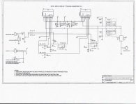
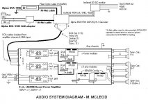
Attached is the schematic of the amplifier modules. In my second post, a system diagram including the whole amplifier and source units, etc.
I will try again all suggestions above, and recheck how I applied Perry's suggestion.
Thank you again!
Sorry for the delayed response had to scan my document + scanner use problems.
Attached is the schematic of the amplifier modules. In my second post, a system diagram including the whole amplifier and source units, etc.
I will try again all suggestions above, and recheck how I applied Perry's suggestion.
Thank you again!
Attachments
As a side note, originally I thought had resolved the noise. The source, the PXA-H701, measured continuity to chassis ground on its RCA shields.
I made a DC-DC isolation module, and isolated all power & ground to the Alpine PXA and 90% of the noise was gone. Increasing the input level on the amps revealed the ground loop noise, which is why I am here again!!
If I connect only one RCA or only one pair of RCA connectors from the source, each one/pair on a separate SMPS/amp, I don't hear noise. However any additional RCA connector in used per each SMPS/amp set reveals the noise.
My amplifier is really like 3 amps in one: all 3 SMPS outputs are isolated from chassis ground and each other, with a star ground configuration to the power connections.
All RCAs internal to the amp are direct to the PA100s & isolated from the amp chassis ground with the exception of the braided RCA shield, connected on only one end to amp chassis (chassis gnd). The reduced EMI picked up if I use cooling fans.
When the system is on I can verify no continuity to chassis gnd on the RCAs. I also disconnected the control cables going to the head unit (to break any ground connections there) and somehow still the noise was still present.
Right now I am having to run one one pair of audio per each SMPS + the sub channel to avoid noise.
I'm willing to try anything and really appreciate you guys helping me.
Attachments
MartyM said:
I made a DC-DC isolation module, and isolated all power & ground to the Alpine PXA and 90% of the noise was gone. Increasing the input level on the amps revealed the ground loop noise, which is why I am here again!!
I'm willing to try anything and really appreciate you guys helping me.
I have done a similar DC to DC setup a long time ago back in 1993. and it worked well. The main difference is I DC to DC powered the entire low level system and isolated the antennas with blocking caps.
It was for a show car install, and the owner was a engineer, so he was looking to go as esoteric as possible. It worked. Plastic plates and mounting hardware. All grounds tied to a central point off the DC to DC converter regulator setup.
It was not cheap, but the client was happy with the results. He got a room full of trophies for the all the effort 2 years in a row. And no noise or hiss issues at all, ever.
But it was a very extreme situation, where SQ was the goal and the sky was the limit...
With 3 isolated power supplies, you shouldn't be having ground loop issues.
Are all of the supplies driven by the same IC? If not, are the ICs sync'd together?
If you disconnect all RCA cables from the alpine processor, do you read 0 ohms between all of the shields on the processor?
Are all of the supplies driven by the same IC? If not, are the ICs sync'd together?
If you disconnect all RCA cables from the alpine processor, do you read 0 ohms between all of the shields on the processor?
Hi everyone-I tried all of the recent suggestions (above) and none worked.
Perry-yes, I have continuity (0 Ohms) between all RCA shields on the output of the Alpine PXA, and also to its ground wire, which now is normally isolated from chassis ground since I'm using my DC-DC isolator.
If I could get the amplifiers to stop popping fuses when I use ground loop isolators, I would settle for using those on the offending input pairs and that will allow me to use the unrestricted/unbuffered inputs on primary channels without noise.
I tried this earlier (using my Stinger gr. loop isolator) and had no noise, but popped 3 fuses either on amp start-up or at the end of music tracks. Also heard high-frequency ringing in the channels where they were used. (I'm assuming it's because the PA100 amplifier design has an input capacitor of 1uF and is causing oscillation?).
Thanks...the search continues....
richie00boy said:Surely a proper electronic balanced input/output scheme would prevent a hum loop though? If the hum is due to noise on the shield or different earth potentials (either of these cases superimposing unwanted voltage on the earth and only the earth) then the balanced input would reject it. e.g. say there is 2V of signal and 1V of rubbish on the sheild, at one point in time one side of the balanced input would see 1V and the other 3V therefore the output would be 4V which is correct.
The short answer is NO.
What you have to remember is that balanced lines work on a "common mode noise rejection" principle.
A typical balanced line cable has two active conductors - hot and cold, plus the braid or shield which is generally ground.
The source end of the system supplies two signals - they are the same audio, but they are 180° out of phase with respect to each other.
If you look at the hot and cold lines, when one is swinging maximum negative, the other is swinging maximum positive. Just think "mirror image".
Now, the secret with common mode rejection is this: when a balanced cable picks up unwanted noise, it picks it up EQUALLY in both conductors. Whatever signals on the balanced line are equal in amplitude and phase are the ones that are rejected.
Only the signals that are equal in amplitude but 180° out of phase will pass through.
If you have a ground loop that exists due to eddy currents in the shield or the braid, then it is only ONE connection, and therefore out of the picture as far as common mode rejection goes, because the balancing only takes into consideration the signals that appear on the HOT and COLD lines.
There are plenty of instances I have seen where people have lifted the shield or ground connection of a balanced line, to try to cure a hum loop or grounding issue.
I've even seen the earth pins of mains plugs cut off with sidecutters in a desperate attempt to quieten a noisy sound system that uses balanced connections all the way throughout.
The whole idea of balancing is to stop unwanted noise (mains hum, RF, static discharge etc) getting in to cables on their journey from the source to the amplification.
Balancing does not solve ground loops or earthing problems.
Thanks for the detailed explanation, but I'm aware of how a balanced line works. I tried to indicate that knowledge with my comment on the noise being solely on ground but maybe I didn't make it clear enough.
Taking your example (and my illustration again) if the noise is on ground then it is common to both hot and cold, as hot and cold are both referred to ground with an electronic balanced line. This is what I was highlighting with the voltages I quoted as examples.
There are several ways in which electronic balanced lines can be done, both at the receiving end and the sending end. Maybe the loop problems you have seen are due to some kind of wiring error, or as CMRR of an electronically balanced line is limited to around 90dB in reality it is also possible that some of the ground loop will bleed though and in a very high power system this could be audible when no music is playing.
Thanks to everyone for trying to help-it was unfortunate I was not able to resolve the issue with any of the items mentioned.
Although extreme, I added one more SMPS inside the amp (one SMPS per RCA pair),still isolated, which reduced the noise even further, to a point where reducing the gain will make the noise inaudible.
Since the ground loop isolator tested caused the amp modules to isolate I'll post that in the chip amp forum for assistance, where it's more appropriate.
Thanks! Too bad it's not corrected yet
Perry, I do need to correct one statement I made earlier after making these changes and retesting.
Although YES all secondaries are isolated, the remaining (reduced) noise occurs when one the 2nd RCA of a pair is plugged in its corresponding jack. When only one is in, seems to be ok.
On an additonal note, I'm going to go ahead with side plans and isolate the whole high-level system, not just the DSP/EQ, from chassis ground as I had thought to do anyway (did not appear to matter earlier when tested, but I'll verify tomorrow).
richie00boy said:
Taking your example (and my illustration again) if the noise is on ground then it is common to both hot and cold, as hot and cold are both referred to ground with an electronic balanced line. This is what I was highlighting with the voltages I quoted as examples.
Ok, well your theory is good except for two issues:
1) noise that appears on the ground is NOT common to both hot and cold. If noise that appears on the ground does manage to get through to the hot and cold, then it will be rejected by the balancing, but the noise can still find its way into the amplification stage through the grounding in the amplifier. Noise from a hum loop such as this is NOT being produced by the balanced input.
2) Hot and cold are not referenced to ground AT ALL in a balanced system.
You can have a balanced line that doesn't even have a ground, and it will work perfectly. The telephone in your house is a good example. It travels miles on a twisted pair and generally exhibits no hum or noise at all.
You can have residual noise on the shield of a balanced cable, yet not have it induced in the hot or the cold. Therefore, no cancelling occurs because there is nothing to cancel!
Invariably, hum and ground loops which appear on the shield of a cable pass through the groundplane or zero volt rail of the amplifier PCB - and this gets into the audio path and becomes audible.
At this level, the balanced line has nothing to do with the system, therefore it has no effect on getting rid of the noise.
Your explanation is spot on, but the unfortunate downside of active balancing is that hot and cold ARE referred to ground by the op-amp(s).
Doug Self has a good explanation on his website, I've just been on try give you the link but unfortunately the pages are down for refurbishment at the moment.
Doug Self has a good explanation on his website, I've just been on try give you the link but unfortunately the pages are down for refurbishment at the moment.
Ok, something doesn't add up here.
Using op-amps in balanced input stages, I know of no referencing to ground except on the output of the op-amp. [By the time the audio gets to there, the common mode rejection has been dealt with]
The input impedance is almost infinite, and the only reference to ground on the input side are two resistors, one on each leg to lower the input imepdance to an established value (600 ohms for example) otherwise the driving end of the line would be effectively looking into an open circuit.
I could set up a small battery powered line drive unit, with balanced output, send the feed out on two wires across the room to a battery powered amplifier with balanced inputs, have it work flawlessly with no hum or noise, and there isn't a ground wire or reference to be seen anywhere.
All this aside, it doesn't change the fact that balanced lines don't cure ground loop issues.
richie00boy said:That test you propose would be good.
Yes we are digressing a bit
It's not a test, it's a fact. I do it regularly. I have equipment here that runs balanced ins and outs, and I have it go from one side of the room to the other.
I can run it with a twisted pair jumper cable [the stuff you use in phone exchanges for jumpering].
What you have to keep in mind is that balanced audio ONLY needs two wires. This is the whole idea. You don't need a ground.
Grounds are only used for safety purposes and extra shielding. They serve no purpose in the audio path.
- Status
- This old topic is closed. If you want to reopen this topic, contact a moderator using the "Report Post" button.
- Home
- General Interest
- Car Audio
- Good Example Balanced Input Circuit? (Ground Loop Isolation)