Hi!
The schematic is put here just to be commented and, of course together with you to elaborate a correct schematic .....
Found the net a very simple and easy software<LTspice IV> that can quickly draw diagrams .....
I look forward to a scheme proposed by you.
I wish you a nice weekend!
The schematic is put here just to be commented and, of course together with you to elaborate a correct schematic .....
Found the net a very simple and easy software<LTspice IV> that can quickly draw diagrams .....
I look forward to a scheme proposed by you.
I wish you a nice weekend!
Last edited:
Have a nice weekend you too.
45
P.S.
You can look at this schematic and see why your bias will not work:
http://www.drtube.com/schematics/an/ongaku.gif
45
P.S.
You can look at this schematic and see why your bias will not work:
http://www.drtube.com/schematics/an/ongaku.gif
Last edited:
This is better to read...
It is the same driver configuration:
http://www.freeinfosociety.com/electronics/schematics/audio/audionoteneiro.pdf
It is the same driver configuration:
http://www.freeinfosociety.com/electronics/schematics/audio/audionoteneiro.pdf
This is better to read...
It is the same driver configuration:
http://www.freeinfosociety.com/electronics/schematics/audio/audionoteneiro.pdf
I think the changes you referred them and it looks like you're right.
Waiting for an answer from you!
Attachments
I think the changes you referred them and it looks like you're right.
Waiting for an answer from you!
Still not correct!
I have found another schematic. Maybe this is simpler to understand....
Attachments
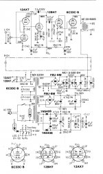
As you can see, you need an additional resistive network connected between the negative supply voltage and ground. You need this network to bias the 12BH7.
The network is made of 2x20K resistors and 1x20K trimmer. They are in series so the current is 190V: 60K = 3.167 mA. The trimmer can go from approx. -63V to -126V.
I repeat that trimmer is necessary to regulate the bias of the 12BH7. Regulating this bias you change the current for the 12BH7 and so the voltage at its cathode. You have regulate the bias until the current flowing in the 12BH7 is {(190V -70 V) / 47K} = 2.55 mA.
So the operative conditions for the 12BH7 are 220+70 = 290V anode voltage and 2.55 mA.
If you look at the 12BH7 curves you can see that for 290V/2.55 mA you need approx. -18V bias (if the cathode voltage is zero!).
In that schematic the cathode is at -70V so the bias for the 12BH7 grid is -88V which you can find rotating the trimmer between -126V and -63V. I suggest to rotate initially the trimmer for the most negative bias because this is also the bias for the power tube. If this is more negative the current will be low and you don't risk any damage....
I hope now this is clear...
45
Last edited:
Hi!
After all the comments coming from your side, I rebuilt the schematic and look again your analysis
Of course, after the schematic will be set, the hardest part is practical work and practical changes, I hope to have a positive result.
Thank you for your time and post here schematically redrawn schematic of the source and the GM70.
Thanks!
Attachments
Hi!
After all the comments coming from your side, I rebuilt the schematic and look again your analysis
Of course, after the schematic will be set, the hardest part is practical work and practical changes, I hope to have a positive result.
Thank you for your time and post here schematically redrawn schematic of the source and the GM70.
Thanks!
No LaZARIOU you are still missing the point!
You need a bias network for the 6L6. In your schematic the bias for U5 is -270V or so....
If you want the cathode of the 6L6 at -80V and the current at 32 mA you need a bias of about - 117V. To do so:
1) you must disconnect R9 from -270V
2) connect a network made of R9b + Trimmer + R9c all in series with the following values:
R9b = 68K
Trimmer = 25K
R9c = 2x82K in parallel
3) connect R9b to -270V
4) connect R9c to ground
5) connect the central terminal of the trimmer to R9
6) you have to change the value of R10 from 2K4 to 5K8
45
Last edited:
I understand what your saying
I was thinking of making an automatic schematic with negativity, but if it is your proposed fix negativity.
It's perfect, I understand and do not forget that the schematic is only theoretical, has been proposed for analysis, so any improvement is welcome.
I have a question: in this case there must decupling(parallel) with an electrolytic capacitor(100uF-470uF) R10, R10 inserted by the negative reaction is not that great??
Thanks!
Attachments
Last edited:
I understand what your saying
I was thinking of making an automatic schematic with negativity, but if it is your proposed fix negativity.
It's perfect, I understand and do not forget that the schematic is only theoretical, has been proposed for analysis, so any improvement is welcome.
I have a question: in this case there must decupling(parallel) with an electrolytic capacitor(100uF-470uF) R10, R10 inserted by the negative reaction is not that great??
Thanks!
First try it like that and then if you are not satisfied make some changes. I cannot tell about the result because I have never used a choke + resistor in series as a load.
A cathode follower has 100% feedback anyway although there is no conventional loop!
For the trimmer look for multi-turn linear trimmer like Bourns etc....0.5W should be enough.
R9b= 68K 2W.
R9c= 2x82K 0.5-1W
Before connecting the GM70 rotate the trimmer more negative than -117 V and then adjust for the correct bias.
Grazie per il vostro interesse e supporto.
Spero che il tempo libero che ho avuto modo di provare un assembly di esempio con questo schema.
E si sa che alla fine qualcosa dal teorico al pratico regole saranno in qualcosa d'altro !!!!.
Ancora una volta grazie per il vostro aiuto!
Una serata piacevole e mi è piaciuto discussione costruttiva con voi.
. Thank you for your interest and support.
I hope that the free time I have got to try an assembly example of this pattern.
And we know that eventually something from the theoretical to the practical rules will be something else !!!!.
Once again thanks for your help!
A pleasant evening and I really enjoyed constructive discussion with you.
Last edited:
Hi
I received the tubes today so now I have the first component for this amplifier.
On the internet I found another diagram for GM70 with 6E5P so if anyone want to comment about it will be nice.
About the OPT we have also some questions: for Ua 950/100mA an OPT with 5k is ok?
Some people say that a 8.2k is need it to obtain at least 40w some say that 5k is enough.
Thanks
Attachments
Hi
I received the tubes today so now I have the first component for this amplifier.
On the internet I found another diagram for GM70 with 6E5P so if anyone want to comment about it will be nice.
About the OPT we have also some questions: for Ua 950/100mA an OPT with 5k is ok?
Some people say that a 8.2k is need it to obtain at least 40w some say that 5k is enough.
Thanks
First, the bias circuit is wrong....
Please have a look at the previous posts or other schematics that use fixed bias.
I don't think you will get 40W out of that circuit. In best case with this solution you can get a bit more than 30W if you go for 1250V anode voltage! More or less like a 845.
At 950V/100mA you will get more likely max 25W with 5K and 20W with 8K.
The math is quite simple because with RC coupling you cannot drive the grid of the GM70 positive. Actually a grid resistor of 50K is already too much for me.
If you don't want to use CCS then you can use an anode choke (i.e. LC coupling) for the driver and further reduce that grid resistor. I wouldn't use more than 33K.
45

- Status
- This old topic is closed. If you want to reopen this topic, contact a moderator using the "Report Post" button.
- Home
- Amplifiers
- Tubes / Valves
- GM70 SE Amplifier