It is compromised as every design is. Nearly every horn is undersized to some extent. This is about the largest cabinet that I could put up with. I tried to get away with just enough bracing as necessary. If I had it to do over there would be a few extra braces in the middle section. The design doesn't really allow bracing of the access panel area. It is by far the most resonant area. Fortunately I will be sitting the subs in such a manner that it is the bottom panel on the floor.
I'd try putting a reflector plate in the back of the mouth where that triangle brace is. I'd bet a buck that'll help with the null.
cheers,
Rev.
I just noticed this edit. That is a good idea. I will try this and see what happens. That is an easy mod if it works. I will also try some strategic placement of damping material and see if that has effect as it is also quick and easy to determine if there is any worth. I am also wondering whether simply placing the access panel on the floor may have some small effect. I took the FR measurement with the sub upside down from normal operation with the access panel up towards the ceiling to get the mouth away from the floor. The sub was in the center of the room and the mic was about 3cm from the plane of the mouth. I used a pretty hot drive level. The access panel area does act quite "live" when putting a lot of level through the horn.
Hi Josh Ricci,
This looks like a great project, thanks for sharing.
As to: "...access panel area does act quite "live"..." I have in the past stiffened panels successfully with permanently attached ribs glued and screwed to the panel, and with removeable ribs going accross the panel attached with bolts, and sealed with foam tape. Putting ribs on the inside of the panel should be an easy retrofit.
Regards,
Well in some ways I am a little disappointed that the top end is not as good as hoped, which would've been merely rough to begin with instead of plain old beat up. I was hoping for it to be useful up to 100hz maybe with help from EQ. The null at 100hz is my biggest let down.
Also the cab is solid as a rock except for the bottom by the access panel where it is quite resonant. I knew this would be the case since the nature of the design didn't really allow any bracing in there and it is right by the driver back wave. The positive about that is that it is the bottom of the cab and in my application will be sitting on the floor with the full 300lb? weight on it. It won't be a problem in that case. I didn't wring the thing out but I did give it a little juice and thus far it doesn't appear that there will be any broken cone from horn pressure shenanigans. Its an angry little beastie. It slappa da bass around like it just don't care mon!. I can't really say that I am surprised by much of this. Par for the course so far.
Josh,
“Little” beastie ?
Impressive build !
You seem to be beating yourself up over a 5 Hz wide 100 Hz (out of the intended pass band) dip.
The DTS-10 has a deeper and wider response dip from around 105 to 125 Hz, and the Gjallerhorn seems to have a smoother response compared to your DTS-10 measurements.
A ramp in the last turn as suggested is worth a try, but probably is not going to cure the null. As far as the access panel vibrations, you might use strategically placed rubber feet in that area, the weight of the cabinet will be concentrated more on the center area if you sand a couple millimeters off the outside four feet. Sand them down until the outside feet are just carrying a few pounds of the weight.
Hope you don’t get cone sag problems, that is a lot of weight hanging down 24/7.
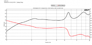
Speaking of your measurements, I notice DSL’s DTS-10 chart averages about 101.5 dB SPL from 20-50 Hz, while your chart averages only 87.5 dB. Taking the 6 dB drive level difference into account still leaves around an 8 dB sensitivity difference between your and Danley’s measurements.
The usual DSL tests are done using 28.3 volts at 10 meters outdoors, but the DTS-10 chart says “Danley Shop”.
I asked Tom Danley about that level disparity in some E-mail correspondence, but he did not reply.
Do you have any idea what would be responsible for the large disparity?
How does the Gjallerhorn sensitivity compare to the DTS-10 ?
The Gjallerhorn seems to roll off a bit steeper below 20 Hz than the DTS-10, any guestimate of how much more clean output it has over the DTS-10 above 20 Hz?
Art Welter
Attachments
I don't have an answer to the dts10 question yet. I am getting ready to do some additional tests on those to try to answer a few questions I have. For one thing I measured the voltage at the amplifier originally and it has 60ft of cable out to the sub. That may account for some of the rest of that difference after the 6db less drive voltage, but no where near all.
First off, love the design! I have followed several of your threads! I found this over on HTS first. Looks amazing and might be a great option for folks who have the room. I do share one concern in regards to cone/spider sag. You might want to contact Thilo at TC Sounds and see what he says, but I do know that their warranty explicitly does not cover sag...
Don
Don
I am not that concerned with sag at this point. It did not get any mention with the TC guys. I'm just hoping the drivers will survive high output use and the cabs actually work well. Besides these will be moved around with some regularity. Also there is nothing that prevents using the subs laying on their sides. I made sure that I had room for them that way as well. Depending on how some things turn out that may be the way that they end up anyway. I don't actually have them placed in what will be the usual area yet still have a lot of fiddling to do before I rearrange all of that. They will be back in a corner with a bunch of other gear either on or around them and it will be a tight fit.
On another subject .
How does everyone calculate delay needed for a TH? For a FLH this would be easy but since the TH is driven from 2 different parts of the path length is it still the same or modified to be somewhat shorter due to the placement of the tap in?
Art,
Thoughts on the previous conversation? Care to share what you are thinking? You usually tell it the way that you see it. BTW I saw your posts at another forum on a related subject but did not comment. I believe they were closed.
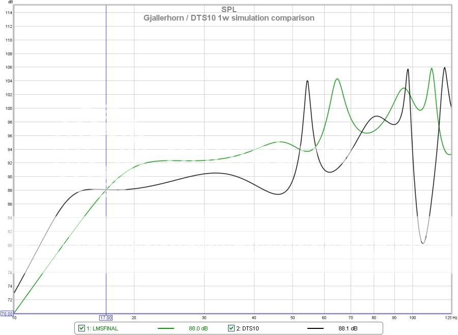
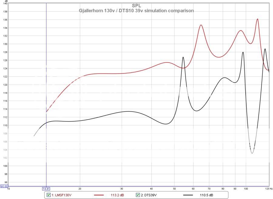
Art here is some comparison via simulation of the DTS10 versus this horn. This isn't exactly an apples apples deal. The Gjallerhorn is 16% larger, has a higher 17hz versus 14hz loading, has 18% more cone area and 2.3X the total driver displacement and is in all likelihood heavier as well. Also this is just simulation, real world results will be a little or maybe even a lot different especially at high power.
Output at 1m with drive voltage corresponding to 1w into the minimum impedance in the passband
Excursion at above drive level. Black is DTS10
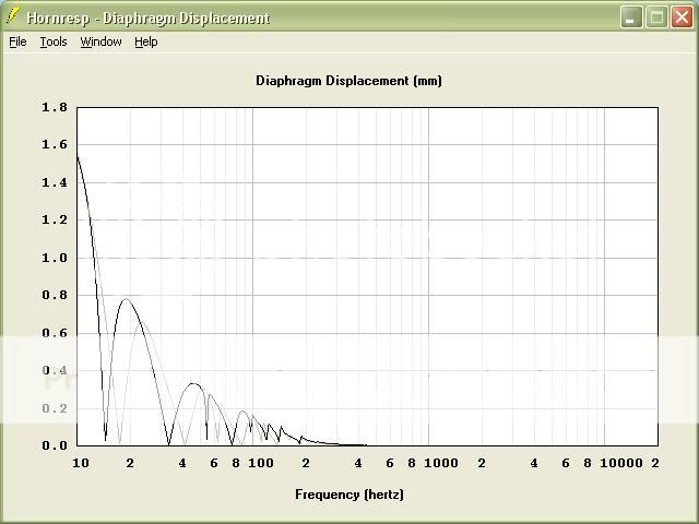
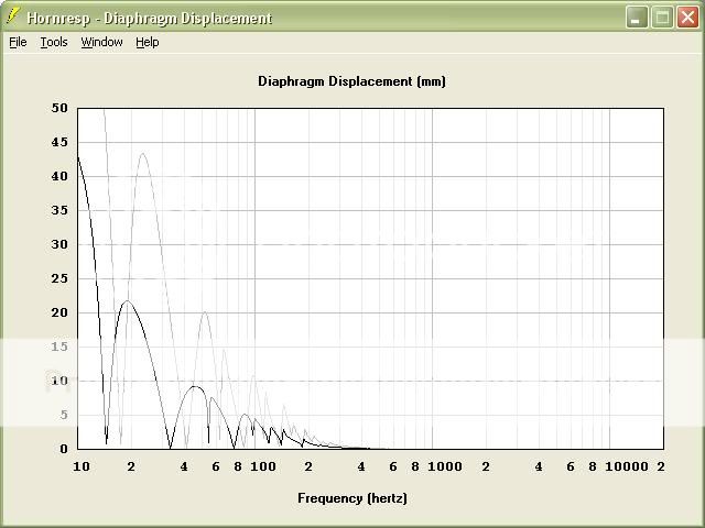
Output at 130v for Gjallerhorn and 39v for DTS10 (drivers parallel)which brings the excursion near to xmech at the highest excursion peak above the corner.
Excursion at above drive level.
Output at 1m with drive voltage corresponding to 1w into the minimum impedance in the passband
Excursion at above drive level. Black is DTS10
Output at 130v for Gjallerhorn and 39v for DTS10 (drivers parallel)which brings the excursion near to xmech at the highest excursion peak above the corner.
Excursion at above drive level.
I tried out a few things to see if I could get some worthwhile improvement yesterday.
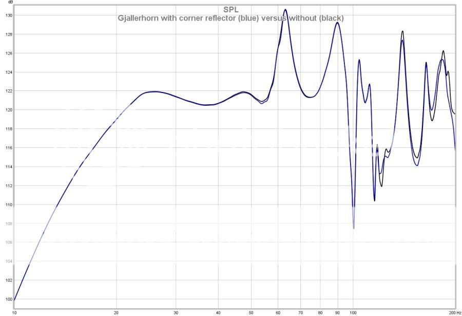
I tried adding a reflector panel at 45 degrees in the last corner before the driver to see if it would affect the upper end response and perhaps help out at 100hz...No dice. Negligible impact. Scratch that from the list.
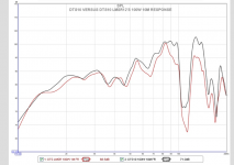
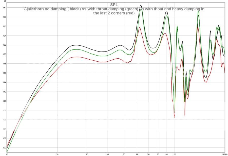
While I was at it I tried some damping in the throat behind the driver and a generous amount in the last 2 corners before the driver. The throat damping did nothing of note really other than sapping about a db of efficiency. With all of the damping in both corners and in the horn throat it did clean up the response some and knock down the horn resonances at 63hz and 90hz quite a bit. However it also caused an efficiency loss of nearly 3db across much of the bandwidth! No thanks. I don't think the slight improvement is worth the hefty loss of output which is what these big guys are all about. I'd rather just use EQ to knock the edges off. It would be needed with or without the damping anyway. You can see the efficiency losses in this graph.
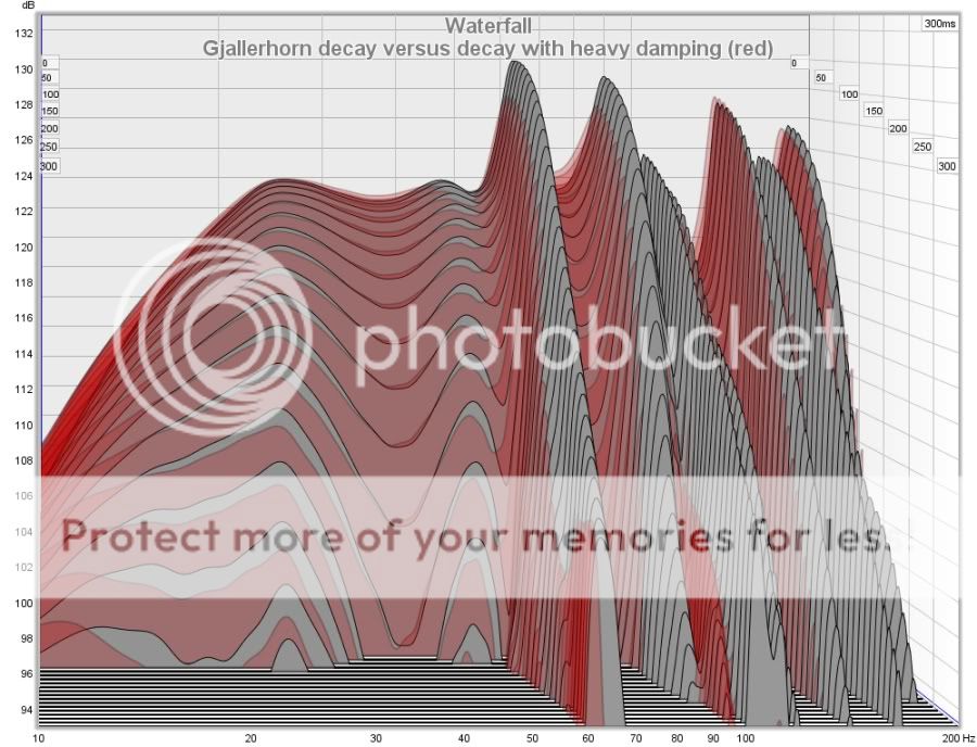
Here is the effect that all of the damping had on the decay of the horn. It did improve it somewhat but once you bring the level back up to match what it was prior to loseing the efficiency it isn't as much as hoped. Again not worth the efficiency sac IMHO.
I tried adding a reflector panel at 45 degrees in the last corner before the driver to see if it would affect the upper end response and perhaps help out at 100hz...No dice. Negligible impact. Scratch that from the list.
While I was at it I tried some damping in the throat behind the driver and a generous amount in the last 2 corners before the driver. The throat damping did nothing of note really other than sapping about a db of efficiency. With all of the damping in both corners and in the horn throat it did clean up the response some and knock down the horn resonances at 63hz and 90hz quite a bit. However it also caused an efficiency loss of nearly 3db across much of the bandwidth!
No thanks. I don't think the slight improvement is worth the hefty loss of output which is what these big guys are all about. I'd rather just use EQ to knock the edges off. It would be needed with or without the damping anyway. You can see the efficiency losses in this graph.
Here is the effect that all of the damping had on the decay of the horn. It did improve it somewhat but once you bring the level back up to match what it was prior to loseing the efficiency it isn't as much as hoped. Again not worth the efficiency sac IMHO.
Yes, that thread was closed, then Tom E-mailed me and we had some further discussions. The discussions ended when I sent him a screenshot of your DTS-10 measurements compared to his (or rather Ivan's).On another subject .
How does everyone calculate delay needed for a TH? For a FLH this would be easy but since the TH is driven from 2 different parts of the path length is it still the same or modified to be somewhat shorter due to the placement of the tap in?
Art,
Thoughts on the previous conversation? Care to share what you are thinking? You usually tell it the way that you see it. BTW I saw your posts at another forum on a related subject but did not comment. I believe they were closed.
My observations regarding DSL's sub charts is the TH-115 and TH-118 are 3-6 dB high compared to other industry standards. Your DTS-10 measurements are even further off.
A side by side comparison of a DSL sub to any industry standard with published charts would confirm or refute my observation. A few months ago Ivan Beaver said he would do a test with some EAW cabinets in shop, but has been very busy and has not.
As far as calculating TH delay, the path length is a good starting point.
The two TH alignments that I extensively tested came out with the top cabinets delayed just a bit shorter than the TH path length, lucky for me as the delay in the DRPA is only slightly longer than the Keystone 18" sub.
I looked at the amplitude response with sub polarity reversed, at the acoustic crossover point the amplitude will be at minimum. I measured about an 18 dB null when the time was correct, then put polarity back to "normal", which is the cone driving into the long path length with positive polarity to the + (cone driving away from the magnet and basket).
I'd need new processors if I decide to build a Gjallerhorn..
Art
Well. Unless I have made some huge mistake the dts10 efficiency is right where I have it. Using my bastardized 1w method. I have measured this probably 4 times now. I have the dts10's set for one more round this weekend to answer a few other things. I double checked yesterday and I did indeed have the drivers in parallel as thought. Also of note is that the simulation of the dts10 comes in right about where the measurements I have done do. I can't get the HR sim to show this extra efficiency either. Everything that I have on them matches up pretty well as I see it. If we can't even get a perfect scenario on the computer to come close to matching the quoted sensitivity then something is not right. I have heard mention that there is an extra 3 or 4 db that no one can seem to come up with. If you add the roughly 6 db for moving to a 2.83 v signal this is about how far from the mark it would be. The Data-Bass info showing about 10db down in general with about 6 accounted for.
Bjorno,
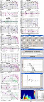
That is a lot of data in your screen attachment! Is difficult to follow exactly what the progression is/was. At the end I see that you are attempting to address the uber TH ringing at 63hz in this guy and the impulse or time domain response, notably the bump prior to the peak. I recognize the basic data and the addition of some EQ but what is the difference applied in the green and blue traces? One thing is for sure...Any time there is a radiator in one spot and another 10-20ft further away there will be some wonky time domain issues!
That is a lot of data in your screen attachment! Is difficult to follow exactly what the progression is/was. At the end I see that you are attempting to address the uber TH ringing at 63hz in this guy and the impulse or time domain response, notably the bump prior to the peak. I recognize the basic data and the addition of some EQ but what is the difference applied in the green and blue traces? One thing is for sure...Any time there is a radiator in one spot and another 10-20ft further away there will be some wonky time domain issues!
Bjorno,
That is a lot of data in your screen attachment! Is difficult to follow exactly what the progression is/was. At the end I see that you are attempting to address the uber TH ringing at 63hz in this guy and the impulse or time domain response, notably the bump prior to the peak. I recognize the basic data and the addition of some EQ but what is the difference applied in the green and blue traces? One thing is for sure...Any time there is a radiator in one spot and another 10-20ft further away there will be some wonky time domain issues!
Finally, another person who uses the word Wonky! Most of that data was overwhelming for me! There is just so much going on with these horns! I am working hard to understand. I am watching this very closely as I might build one of these for my LMS once I see some final results and someone else has done all the work for me
Don
Gjallerhorn: If using a 5 band min-phase parametric EQ
Hi,
Sorry for being late with this answer:
The cerise color(~red),the first upper left plot is the total simulated FR for the TH.
Green is the resulting FR after splicing the IR into two parts:Blue is the Pre-pulse FR i.e. the starting negative amplitude that precedes the positive green Main-pulse FR.
Time t=0 is set to when the Main-pulse has propagated from the driver front to the rear side.
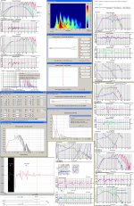
Here's more to chew on:
b
Bjorno,
That is a lot of data in your screen attachment! Is difficult to follow exactly what the progression is/was. At the end I see that you are attempting to address the uber TH ringing at 63hz in this guy and the impulse or time domain response, notably the bump prior to the peak. I recognize the basic data and the addition of some EQ but what is the difference applied in the green and blue traces? One thing is for sure...Any time there is a radiator in one spot and another 10-20ft further away there will be some wonky time domain issues!
Hi,
Sorry for being late with this answer:
The cerise color(~red),the first upper left plot is the total simulated FR for the TH.
Green is the resulting FR after splicing the IR into two parts:Blue is the Pre-pulse FR i.e. the starting negative amplitude that precedes the positive green Main-pulse FR.
Time t=0 is set to when the Main-pulse has propagated from the driver front to the rear side.
Here's more to chew on:
b
Attachments
Last edited:
I have done some outdoor testing on one of the cabs. I have attached the maximum long term output available using a 10-120hz, 24 second long, ascending sine wave sweep recorded outdoors at 2 meters ground plane. Amplifier is a Powersoft K10 on 240v. There is a good deal of thermal compression in evidence so CEA2010 burst testing should show peak output numbers somewhat higher still. There is no lack of output here. The driver did not grenade, or shred the cone or develop coil rock or any of that. If anything the driver has a much harder time dealing with the power themally. The power compression sweeps are 9 24 second long ascending sweeps back to back with each having the level increased by 5db over the last. This is ended when the sub exhibits clear distress signals. This was immediately followed by 1/48 octave sine burst distortion testing using the STEPS program which takes about 5 min to complete the full measurement. There were 9 of these run back to back at the same input levels as used during the power compression sweep tests. By the end of this the motor was extremely hot and there was the smell of hot voice coil adhesive (Mmmmm.) and some darkening. This was on a visciously hot 95degree day in direct sunlight as well. I ended up running a greatly reduced power 20hz sine wave for a few minutes, which is at the in passband excursion maximum to help cool the motor down afterwards. This is far far more punishment than even the worst real world, long term duty it might ever be asked for.
After testing a DTS10 a couple of times and switching to totally different much beefier drivers and testing that and now testing this tapped horn I have noted that the usual peaks that are seen at low volumes and in simulation get heavily compressed and squashed at the highest playback levels. I am ruling out amplifier clipping due to having plenty of power on hand to either fry or launch the cones at will. It appears that there is either severe compression occuring in the drivers or that there is some sort of acoustic limiting or compression occuring inside the horn itself. i am leaning towards some of the later. Thoughts?
Also after taking this thing a little bit past the limit truthfully I wish that I had beefed the cabinet up a little more and used more bracing. At the very highest sweep levels the cab sounded as if it may blow a seam and developed a buzz in a few narrow frequency ranges near 63hz and about 85-90hz. This isn't evident if you knock the output back to sane levels. I doubt they would be notable with real broadband content either. Outdoor sine waves are pretty unforgiving on exposing rattle and buzz issues. There must be an enormous amount of power being developed inside of this cab. I think I may have underestimated how much.
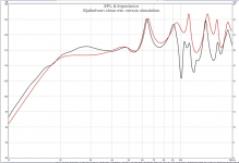
Now this is a real curiosity. When I first put the cabs together and applied power I took some close mic graphs. These all show a 100hz dip that was not apparent in the simulation. I then ran the pair lightly in a pa set-up for a few days. Fast forward...I get one of them outside to test it and lo and behold the 100hz dip is gone and between 90-110hz the response has changed. The 100hz dip is no longer there. I freak out thinking perhaps I had damaged something in this cab, or the driver, or both, which wouldn't have been out of the realm of possibility considering the beating bestowed on it, so i run inside and take a measure on the other cab and it is now missing the 100hz dip too. That one hasn't been used very hard at all. I thought that perhaps I somehow had EQ engaged during the original measurements but there is no way. The drivers were brand new and had never been above about 2v so perhaps they had a major break in and this is responsible but I find that a hard pill to swallow. The cabs are 13ply BB with pocket screws and are PL'd together and built by a professional cabinet shop who's owner owns DTS-10's and is familiar with speakers so I have a hard time believing that a panel came loose and shifted enough to cause the response change either. I am at a loss to explain it really. I have attached a couple of measurements illustrating this as well. The 100hz notch is easily seen in the original measurement. The other one is the current response where there is no longer a 100hz dip. Very odd. Atleast it is a response improvement.


After testing a DTS10 a couple of times and switching to totally different much beefier drivers and testing that and now testing this tapped horn I have noted that the usual peaks that are seen at low volumes and in simulation get heavily compressed and squashed at the highest playback levels. I am ruling out amplifier clipping due to having plenty of power on hand to either fry or launch the cones at will. It appears that there is either severe compression occuring in the drivers or that there is some sort of acoustic limiting or compression occuring inside the horn itself. i am leaning towards some of the later. Thoughts?
Also after taking this thing a little bit past the limit truthfully I wish that I had beefed the cabinet up a little more and used more bracing. At the very highest sweep levels the cab sounded as if it may blow a seam and developed a buzz in a few narrow frequency ranges near 63hz and about 85-90hz. This isn't evident if you knock the output back to sane levels. I doubt they would be notable with real broadband content either. Outdoor sine waves are pretty unforgiving on exposing rattle and buzz issues. There must be an enormous amount of power being developed inside of this cab. I think I may have underestimated how much.
Now this is a real curiosity. When I first put the cabs together and applied power I took some close mic graphs. These all show a 100hz dip that was not apparent in the simulation. I then ran the pair lightly in a pa set-up for a few days. Fast forward...I get one of them outside to test it and lo and behold the 100hz dip is gone and between 90-110hz the response has changed. The 100hz dip is no longer there. I freak out thinking perhaps I had damaged something in this cab, or the driver, or both, which wouldn't have been out of the realm of possibility considering the beating bestowed on it, so i run inside and take a measure on the other cab and it is now missing the 100hz dip too.
That one hasn't been used very hard at all. I thought that perhaps I somehow had EQ engaged during the original measurements but there is no way. The drivers were brand new and had never been above about 2v so perhaps they had a major break in and this is responsible but I find that a hard pill to swallow. The cabs are 13ply BB with pocket screws and are PL'd together and built by a professional cabinet shop who's owner owns DTS-10's and is familiar with speakers so I have a hard time believing that a panel came loose and shifted enough to cause the response change either. I am at a loss to explain it really. I have attached a couple of measurements illustrating this as well. The 100hz notch is easily seen in the original measurement. The other one is the current response where there is no longer a 100hz dip. Very odd. Atleast it is a response improvement.
Last edited:
Josh,After testing a DTS10 a couple of times and switching to totally different much beefier drivers and testing that and now testing this tapped horn I have noted that the usual peaks that are seen at low volumes and in simulation get heavily compressed and squashed at the highest playback levels. I am ruling out amplifier clipping due to having plenty of power on hand to either fry or launch the cones at will. It appears that there is either severe compression occuring in the drivers or that there is some sort of acoustic limiting or compression occuring inside the horn itself. i am leaning towards some of the later. Thoughts?
Now this is a real curiosity. When I first put the cabs together and applied power I took some close mic graphs. These all show a 100hz dip that was not apparent in the simulation. I then ran the pair lightly in a pa set-up for a few days. Fast forward...I get one of them outside to test it and lo and behold the 100hz dip is gone and between 90-110hz the response has changed. The 100hz dip is no longer there....
At least it is a response improvement.
That is some serious LF level, even for a cabinet that size !
No wonder the driver was hot, and with that much thermal mass and a high ambient temperature, it probably stayed hot for a long time.
You seemed to be beating yourself up over a 5 Hz wide 100 Hz (out of the intended pass band) dip two weeks ago, now that it is gone you complain ;^) ?
I have found indoor measurements to be very difficult to reproduce, unless every detail has been meticulously recorded.
Did you exactly repeat the measurement microphone location, speaker orientation and room position as when you measured the dip?
I am curious if the weight of the cone will affect large signal results more if the cone is vertical rather than horizontal, of course loading will be slightly different in either orientation.
What orientation of the cabinet did you try in the outdoor test ?
In post #12 of :
http://www.diyaudio.com/forums/subwoofers/185588-keystone-sub-using-18-15-12-inch-speakers-2.html
I noted a similar observation to what you have noticed with your tapped horns, high power sine waves reduced upper peak levels using the BC18SW115-4 driver .
However, using two Lab12s in the same tapped horn did not reduce the upper peak.
Testing with pink noise rather than sine waves the response of both looked the same at low and high power.
Have you done any side by side music listening between the Gjallerhorn and the DTS-10?
Art
- Status
- This old topic is closed. If you want to reopen this topic, contact a moderator using the "Report Post" button.
- Home
- Loudspeakers
- Subwoofers
- Gjallerhorn