To all:
As I read a few of the various posts regarding things like resistor selection, CCS and Diode placement, heat dissipation, etc. it leads me to a question.
Is there any rule of thumb regarding physical separation between components and a metal chassis / other grounding point?
Here's why: I seem to remember reading somewhere on TubeLab.com that there should be a "minimum" distance from some components and the chassis, which justifies mounting the tube sockets on the silkscreened side of the board, but most of the high heat release components (cathode resistors, CCS TO-220 units and their heat sinks) on the "other" side.
In normal circumstances, this is not the ideal for heat transfer and may lightly toast the PCB over time.
I'd like to mount some of the higher heat dissipation items (wirewound resistors and the CCS TO-220 packages) on the TOP side, but clearances are tight due to the limited clearance of the tube sockets. I believe there could be between 10-15 mm (about 3/8 to 7/16 inch) to play with from the board top side to the underside of a chassis plate (say 2.5 to 4mm thickness)
Any guidance from the forum?
Thanks.
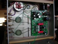
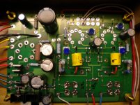
I've built my TubelabSE the way you are describing, with the components on the bottom and the tube sockets on the top, and the PCB is "hanging" from the top deck on standoffs.......at approx the distance that you reference. It works fine, although you need to triple check the semiconductors pin outs when installing them on the bottom, same with cap polarity.
I machined a couple of vent slots in the top deck above the heatsinks. The is a TubelabSE not a Simple Single Ended board so everything's a bit different.
I would personally be a little uncomfortable with HV resistors, etc being on the topside, close to the deck but YMMV.
I machined a couple of vent slots in the top deck above the heatsinks. The is a TubelabSE not a Simple Single Ended board so everything's a bit different.
I would personally be a little uncomfortable with HV resistors, etc being on the topside, close to the deck but YMMV.
Attachments
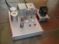
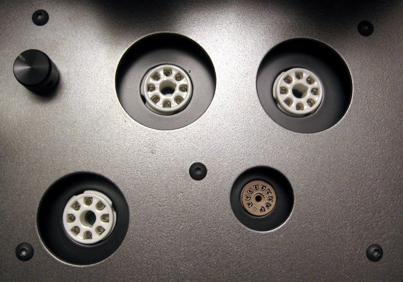
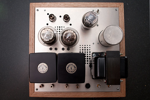
I mounted mine up top because the ventilation is better. That is because in my case, there is a gap around the inset tube sockets to promote convection. The hot air above the PCB is pulled through the holes, whereas any heat under the PCB has no active air current to pull it away.
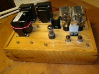
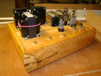
Here is a picture of all of the pieces. It was made out of mostly hardware store aluminum stock (u-channel and angle). The extra plate is just a thin sheet of aluminum to act as a guard for the over-sized holes. You may notice that it has a few extra holes to ventilate hot spots on the PCB.
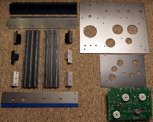
More about the construction:
Tubelab Simple SE – Construction – metaruss
More about the construction:
Tubelab Simple SE – Construction – metaruss
I've built my TubelabSE the way you are describing, with the components on the bottom and the tube sockets on the top, and the PCB is "hanging" from the top deck on standoffs.......at approx the distance that you reference. It works fine, although you need to triple check the semiconductors pin outs when installing them on the bottom, same with cap polarity.
I machined a couple of vent slots in the top deck above the heatsinks. The is a TubelabSE not a Simple Single Ended board so everything's a bit different.
I would personally be a little uncomfortable with HV resistors, etc being on the topside, close to the deck but YMMV.
I know this is old but I have a question that directly relates to it:
Is there anything to stop me putting everything on the top of the PCB EXCEPT the tube sockets and then mounting it upside down?

I soldered the 5 terminal regulator to its pads, laying flat off the back of the board.
So, all the pins are fully extended, not bent, not cut, And the ends are soldered to the pads. Then the regulator extends past the pcb where I have it mounted to a heat sink.
(which is why on the photo of mine a page back, the vent holes by the regulator area extend way out past where the PCB is)
So, all the pins are fully extended, not bent, not cut, And the ends are soldered to the pads. Then the regulator extends past the pcb where I have it mounted to a heat sink.
(which is why on the photo of mine a page back, the vent holes by the regulator area extend way out past where the PCB is)
Moggi: When populating the bottom of the PCB, triple check the polarity of anything that has polarity, like diodes, electrolytic caps, mosfets, and the tricky one, the filament regulator (5 legged critter).
So when I put it on the bottom the negative terminal is soldered to the same 'hole' it would have been on top, right?
")
- Status
- This old topic is closed. If you want to reopen this topic, contact a moderator using the "Report Post" button.
- Home
- More Vendors...
- Tubelab
- General Tubelab PCB question...