soongsc said:
Were there any other tradeoffs that you had considered when deciding not to use an elliptic type mouth?
No.
The picture seems to be the lower frequency modes.Jmmlc said:Hello Earl,
I agree with you about the required behavior for the material to build horns and waveguides.
Your's is surely interesting for internal damping (I recommanded many times to Marco Henry to use micro balloons in his material).
Thickness of the wall along the axis is very important too to damp vibration of the whole structure. Most often molded horns possess a constant thicness of their walls and while this is this for sure an easy solution it is surely a bad thing when it comes to virbation damping.
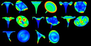
here is a FEM simulation of how strains a flimsy theorical Le Cléac'h horn:
http://www.musique-concrete.com/matP/mat15.jpg
from such studies we can obtain information on the right places along the horn's wall where we have to increase the thickness.
Best regards from Paris, France
Jean-Michel Le Cléac'h
Hello Soongsc,
Attached picture will show you more modes.
Best regards from Paris, France
Jean-Michel Le Cléac'h
Attached picture will show you more modes.
Best regards from Paris, France
Jean-Michel Le Cléac'h
soongsc said:
The picture seems to be the lower frequency modes.
Attachments
Note the location of the strong modes are probbably related with Dr. Geddes describes as sources of HOM. Is this device axisymmetric?Jmmlc said:Hello Soongsc,
Attached picture will show you more modes.
Best regards from Paris, France
Jean-Michel Le Cléac'h
Hello Soongsc,
There is probably very few or no relation between the different vibration modes of the horn walll as illustrated in the FEM simulations I show, and the way the wave propagate in the air inside the horn .
The vibration modes as illustrated are more related to solid(ian) propagation. That's means that if the coil reproduces a pulse, a part of the energy will be transmitted through the body of the compression driver then through the material constituting the horn's wall. If the horn vibrate and specially near the mouth, then there will be some intermodulation between the waves emitted by the wall and the waves propagating through the air inside the horn.
Also in the worst case, we can see on the pulse response of a driver monted on a horn a small pulse arriving before the main pulse. This is because speed of sound through most solids is something around 10 times the speed of sound.
Most often people gives a small tapp with their finger to the mouth of a given horn and say "oh! it rrings like a bell". This is faintly useful. It is far more realistic to tapp the horn near the throat.
Now imagine you vibrate the horn near its throat, the vibration will strain (= induce deformation in) the wall of the horn. This is a very small deformation. The graphs I gave show that deformation multiplied by a large factor in order to see clearly how the wall of the horn vibrate for a given mode. A horn having a very thin wall will lead to larger modal vibrations than a horn having a thick wall but the shape of the deformation will be the same.
The horn is axisymetric.
Best regards from Paris, France
Jean-Michel Le Cléac'h
soongsc said:
Note the location of the strong modes are probbably related with Dr. Geddes describes as sources of HOM. Is this device axisymmetric?
If the horn is vibrating at the lip, then it's acting like a direct radiator with a cone breakup mode to some degree. This I beleive is the HOM normally measured. I have not seen any data showing that HOM is created by air moving in the horn. Probably if there is data showing horn/guides of the same shape but very different structural modes that have the same HOMs, then I will be convinced.
I am fully aware how FEA software present deformation graphically. However, if the deformation is larger, it means louder ringing and longer duration. Smaller deformation due to material thickness means lower ringing and shorter duration.
Realistically, FEA search for structural modes should be done in multiple ways to gain better understanding of how the modes will change. One is having the body totally free, another is fixing it at the throat, yet another is adding the driver to the end of the throat with the whole assembly free.
Hello Soongsc,
IMHO you are mixing phenomenons which are very poorly correlated so I'll let Earl reply about the HOM relation with the vibrational modes of the horn...
Our FEM study followed the method you described but the example shown are only for a mouth which is not clamped.
Best regards from Paris, France
Jean-Michel Le Cléac'h
soongsc said:
If the horn is vibrating at the lip, then it's acting like a direct radiator with a cone breakup mode to some degree. This I beleive is the HOM normally measured. I have not seen any data showing that HOM is created by air moving in the horn. Probably if there is data showing horn/guides of the same shape but very different structural modes that have the same HOMs, then I will be convinced.
I am fully aware how FEA software present deformation graphically. However, if the deformation is larger, it means louder ringing and longer duration. Smaller deformation due to material thickness means lower ringing and shorter duration.
Realistically, FEA search for structural modes should be done in multiple ways to gain better understanding of how the modes will change. One is having the body totally free, another is fixing it at the throat, yet another is adding the driver to the end of the throat with the whole assembly free.
soongsc said:
If the horn is vibrating at the lip, then it's acting like a direct radiator with a cone breakup mode to some degree. This I beleive is the HOM normally measured. I have not seen any data showing that HOM is created by air moving in the horn. Probably if there is data showing horn/guides of the same shape but very different structural modes that have the same HOMs, then I will be convinced.
HOMs are purely a form of mode that exists within the air of the wvageuide. This is how they are defined. They have been shown to exist by numerous researhcers.
soongsc said:
I am fully aware how FEA software present deformation graphically. However, if the deformation is larger, it means louder ringing and longer duration. Smaller deformation due to material thickness means lower ringing and shorter duration.
The level of ringing and the duration and not coupled things, they are independent.
Structural vibrations of the horn/waveguide would likely be very detrimental due to the different wave velocity in solids as well as the modulation of one frequency by the structural vibration of another. There is no data on this point, but it seems to me that elliminating these structural vibrations is of paramount importance. This is why I don't like free edge waveguides - a clamped edge is much better controlled.
gedlee said:
The waveguide would not have an axisymmetric coverage pattern. Its generally desirable to have a smaller coverage vertically than horizontally. But at the crossover the woofer is going to be axi-symmetric, so its a tradeoff. One that I have choosen not to make.
I get this explanation, but what affect does having the woofer and waveguide's centers being seperated by some distance have on symmetry making this somewhat lessened? For example, isn't the vertical dispersion at fc +/- some overlap narrowed due to the constructive/destructive affects? If this region has a narrower vertical dispersion what real gain is there in going to axi-symmetry at higher frequencies?
This isn't a challenge but a real question.
And its a good question! The fact that there is already a polar aberation in the vertical direction due to spacing certainly does make the argument for comparable patterns in the two sources weaker. But to what extent I simply do not know and have not investigated this. I have used the axisymetric devices for so long and found them to be acceptable that I just stick with them.
You see, unlike many here, I am not one in search of the Holy Grail of Audio. I don't change things just to change them. I solve problems that arise in the most cost effective way. The vertical coverage has not been a problem in my setups, but mostly because I treat the rooms, which IS the better solution.
Initially I did not know how to do an elliptical coverage pattern, but I do now. Some day it may be worth a try, but I suspect that day is very far off since the elliptical shape is dramatically more difficult to tool. Hence its a lot of cost for little potential benefit. There are so many bigger problems arround.
Dr Geddes -
What would happen if you put a ninety degree bend in the throat of a waveguide?
Instinctively this seems like a TERRIBLE idea. But I began to think about it, and wondered if it would be alright if there's no expansion in the bend.
From what I've read here, it seems that HOMs are introduced as the expansion in the waveguide grows; therefore HOMS might not be created in a bend IF the expansion in the bend matches the angle of the compression driver's exit.
Thoughts?
I know this is not ideal, but there are situations where you have to introduce a bend due to packaging.
I would expect a lot of HOMs to be generated, because the sound has to diffract around the corner. I know that in microwave waveguides they do this with a reflection plate and I suspect that at very high frequencies this would also work in acoustics, but at the lower frequencies there will be a lot of diffraction even around this type of corner.
Matching directivity in the vertical and the horizontal planes
One of the main reasons I have always used asymmetrical horns is this very thing. When drivers are stacked vertically on a baffle, nulls form above and below the speaker. If these nulls are placed just outside the horn's pattern, they serve to punctuate pattern control in the crossover region.
When you crossover a direct radiator to a 90 degree CD horn, assuming they are in phase on the forward axis, summing is coherent on-axis as well as off-axis in the horizontal plane even at large angles. So the pattern narrows smoothly from being nearly omnidirectional at low frequencies down to approximately 90 degrees at crossover, where it remains because of the horn.
In the vertical plane, nulls form above and below the speaker at an angle set by the distance between drivers and the frequency range of the overlap in the crossover region. This is usually somewhere between 40-60 degrees. At 20-30 degrees above the forward axis and at 20-30 degrees below the forward axis, nulls develop. These limit directivity to 40-60 degrees, no matter what the horn's directivity is at that frequency.
If the 90 degree horn is axisymmetric, then the pattern widens back up again above the crossover frequency. So the directivity of the horn is not matched to the null angle in the vertical plane, and there is some ripple through that region as a result.
A horn with narrow vertical pattern is useful for matching directivity with the angle of the nulls in the vertical plane. If a horn is used that has 40-50 degree vertical pattern, then the pattern does not widen above the crossover region. In the crossover region, the pattern is set by the off-axis nulls, and above the crossover region, it is set by the horn.
My conclusion is a horn with 90x40 or 90x50 coverage is very useful for loudspeakers with vertically stacked drivers. The dimensions of the drivers (setting the spacing between them) and the crossover points needed all seem to come together using these angles.
JoshK said:I get this explanation, but what affect does having the woofer and waveguide's centers being seperated by some distance have on symmetry making this somewhat lessened? For example, isn't the vertical dispersion at fc +/- some overlap narrowed due to the constructive/destructive affects? If this region has a narrower vertical dispersion what real gain is there in going to axi-symmetry at higher frequencies?
One of the main reasons I have always used asymmetrical horns is this very thing. When drivers are stacked vertically on a baffle, nulls form above and below the speaker. If these nulls are placed just outside the horn's pattern, they serve to punctuate pattern control in the crossover region.
When you crossover a direct radiator to a 90 degree CD horn, assuming they are in phase on the forward axis, summing is coherent on-axis as well as off-axis in the horizontal plane even at large angles. So the pattern narrows smoothly from being nearly omnidirectional at low frequencies down to approximately 90 degrees at crossover, where it remains because of the horn.
In the vertical plane, nulls form above and below the speaker at an angle set by the distance between drivers and the frequency range of the overlap in the crossover region. This is usually somewhere between 40-60 degrees. At 20-30 degrees above the forward axis and at 20-30 degrees below the forward axis, nulls develop. These limit directivity to 40-60 degrees, no matter what the horn's directivity is at that frequency.
If the 90 degree horn is axisymmetric, then the pattern widens back up again above the crossover frequency. So the directivity of the horn is not matched to the null angle in the vertical plane, and there is some ripple through that region as a result.
A horn with narrow vertical pattern is useful for matching directivity with the angle of the nulls in the vertical plane. If a horn is used that has 40-50 degree vertical pattern, then the pattern does not widen above the crossover region. In the crossover region, the pattern is set by the off-axis nulls, and above the crossover region, it is set by the horn.
My conclusion is a horn with 90x40 or 90x50 coverage is very useful for loudspeakers with vertically stacked drivers. The dimensions of the drivers (setting the spacing between them) and the crossover points needed all seem to come together using these angles.

I have not seen any data or reports specifically differentiating what is caused by air withn the waveguide and that generated from structural vibration. could you point me to one paper that does that?gedlee said:
HOMs are purely a form of mode that exists within the air of the wvageuide. This is how they are defined. They have been shown to exist by numerous researhcers.
The level of ringing and the duration and not coupled things, they are independent.
soongsc said:
I have not seen any data or reports specifically differentiating what is caused by air withn the waveguide and that generated from structural vibration. could you point me to one paper that does that?
The same answer that I gave before applies equally well here. Simply read my work.
Re: Matching directivity in the vertical and the horizontal planes
Wayne
This is the convention concept, but I don't completely buy it. You'd have to show me actual measurements or simulations that prove your hand-waving argument before I accepted it. I see no reason to believe that the crossover dip won't be just as deep with the narrow pattern horn as it is with the wide one. Without some better data your just guessing.
Wayne Parham said:
My conclusion is a horn with 90x40 or 90x50 coverage is very useful for loudspeakers with vertically stacked drivers. The dimensions of the drivers (setting the spacing between them) and the crossover points needed all seem to come together using these angles.
Wayne
This is the convention concept, but I don't completely buy it. You'd have to show me actual measurements or simulations that prove your hand-waving argument before I accepted it. I see no reason to believe that the crossover dip won't be just as deep with the narrow pattern horn as it is with the wide one. Without some better data your just guessing.
Just to make sure I'm understanding this correctly, you claim that your book does provide the measured data and explanations that clearly distinguishes which HOMs are generated from driver, air in the waveguide, and structural mode for the same waveguide internal contour from thoat to lip? To me, it sounds we are having a mixup of definitions here. Because you say this:gedlee said:
The same answer that I gave before applies equally well here. Simply read my work.
Then there is somewhere that talks about the diaphragm, which I can't find at the moment.gedlee said:
HOMs are purely a form of mode that exists within the air of the wvageuide. This is how they are defined. They have been shown to exist by numerous researhcers.
But anyway, if we just consider HOM only resulting from air moving in the wave guide, clearly this is not looking at the waveguide design at a system. If your book only focusses on the issue from this aspect, I guess it would be good academic reading material.
Re: Matching directivity in the vertical and the horizontal planes
I know you are aware of this, but I'll explain for others that might not be. What you see when you measure off-axis vertically is the null angle is marked by a very sharp notch at a specific angle surrounded by a wider angle of reduced amplitude. The sharpest point of the notch is where path length differences cause the two wavefronts to arrive exactly 180 degrees out of phase. Wavefronts phased about 30 to either side (150-210 degrees) partially cancel, hence the valley of reduced amplitude.
These null areas are either side of the forward axis, one above the forward axis and the other below it. My approach has always been to use horns with vertical angle inside the nulls. That way, the vertical pattern at frequencies higher than crossover remains approximately equal to the pattern outlined by the nulls.
It's not that the null is any less deep, it's that the pattern above the crossover doesn't widen back up. The vertical angle narrows in the crossover region because of the nulls. A horn with a narrow vertical pattern just doesn't widen back up at HF, that's all. That's why I think it is good to match the vertical null angle to the vertical pattern of the HF horn.
gedlee said:This is the convention concept, but I don't completely buy it. You'd have to show me actual measurements or simulations that prove your hand-waving argument before I accepted it. I see no reason to believe that the crossover dip won't be just as deep with the narrow pattern horn as it is with the wide one. Without some better data your just guessing.
I know you are aware of this, but I'll explain for others that might not be. What you see when you measure off-axis vertically is the null angle is marked by a very sharp notch at a specific angle surrounded by a wider angle of reduced amplitude. The sharpest point of the notch is where path length differences cause the two wavefronts to arrive exactly 180 degrees out of phase. Wavefronts phased about 30 to either side (150-210 degrees) partially cancel, hence the valley of reduced amplitude.
These null areas are either side of the forward axis, one above the forward axis and the other below it. My approach has always been to use horns with vertical angle inside the nulls. That way, the vertical pattern at frequencies higher than crossover remains approximately equal to the pattern outlined by the nulls.
It's not that the null is any less deep, it's that the pattern above the crossover doesn't widen back up. The vertical angle narrows in the crossover region because of the nulls. A horn with a narrow vertical pattern just doesn't widen back up at HF, that's all. That's why I think it is good to match the vertical null angle to the vertical pattern of the HF horn.
- Home
- Loudspeakers
- Multi-Way
- Geddes on Waveguides