pooge said:
An OS waveguide takes a planar wavefront and converts it to a spherical wavefront with the smoothest transition possible, therefore minimizing HOMs. However, the volume velocity across the plane is not uniform across the planar wavefront with commercially available drivers, so some HOMs are generated. This is why Earl went to the foam HOM absorber, because commercially availble drivers do not have a uniform volume velocity, because of the design of the phase plug. Earl designed for the lowest HOMs, and absorbs what is left. The foam is much cheaper than getting some company to redesign a phase plug. We can only hope that this aspect of phase plug design will be addressed in Thailand!!
A conical horn needs to be fed with a SPHERICAL wavefront to keep the HOMs away. Apparently, there are no drivers that will do this.
Quoting myself--and correct me if I'm wrong, Earl--I view your waveguide holistically as a conical horn with a conversion section at the front of the horn to transform a planar wavefront at the throat into a spherical wavefront, as smoothly as possible, to feed the conical horn section with the spherical wavefront to eliminate HOMs in the conical section, while generating as few as possible in the conversion of the wavefront.
DonM said:Can someone comment on the choice of a mid/woofer when using a waveguide for the benefit of other hobbyists such as myself who do not have the appropriate technical knowledge.
DDS has an excellent 90 degree waveguide (ENG1-90) that has a 10” mouth, a cutoff frequency of 900hz, a 1” throat and is 3” in depth.
If one has a mid/woofer in a 2 way that can extend to a high enough frequency without breakup, using a 2nd order crossover at 1,700 hz or a 3rd order at 1,300 hz, can you choose a driver that is either 8”, 10” or 12”?
Thanks,
Don
A 900hz wave is 15" long, so I don't know how that WG can be classified as "excellent". It seems to be compromised. The Summa has a 15" mouth and I'm sure is deeper than 3", and I believe Earl put the XO in the 950hz range.
Hey Earl - hows it going? ("HOMLESS" is killer...)
Best, Fred
here's my lens of choice for HF from 1K8 up w. DE25-8 - hahahaha
Best, Fred
here's my lens of choice for HF from 1K8 up w. DE25-8 - hahahaha
An externally hosted image should be here but it was not working when we last tested it.
Hi
It is true that you need a spherical wavefront to drive a conical corn without HOM’s. There are a few 1 inch drivers that can do this well up to about 60 –70 degrees, like a BMS 4550 and others of that geometry. Also, several 18 sound compression drivers are very good. At least one 1.4 inch drivers can on narrower horns.
You can see the real problem if you plot out the path lengths in the phase plug, they generally produce a converging wave front at summation.
The up side is, a conical horn if driven properly has (down to some size angle relationship) constant directivity and truly emulates a patch of spherical radiation.
Best,
Tom
johninCR said:
A 900hz wave is 15" long, so I don't know how that WG can be classified as "excellent". It seems to be compromised. The Summa has a 15" mouth and I'm sure is deeper than 3", and I believe Earl put the XO in the 950hz range.
The DDS waveguide has received very good reviews and is used by a number of speaker manufacturers. No matter what horn you choose there are always compromises.
My original question concerned matching a waveguide to different sized mid/woofers.
If you notice I left out a 15" woofer since it will compromise the mid range if crossed over at or above 1,000 hz. I have tried it and that is why I'm considering the alternatives.
Of course this is just an opinion.
Don
john k... said:
Not until you just mentioned it. Google it. I guess that is what they are doing, WG to align the tweeter. A pretty obvious solution to the offset problem, but their design is a good example of why I am not really crazy about the idea. In any (analog) TP design there is going to be considerable overlap in the crossover region so driver separation should be kept to a minimum, IMO. Actually, driver separation is one thing I don't like about the use of WGs in any case. Any to be honest I'm not exactly sure what problems a WG on a tweeter really solves other than offset.
As for GD, it's as expected. Goes up as the roll off order goes up. I'm adding more info on applying Eq to woofers with Qts greater than 0.5 and Fs that is acceptable, that is, where shifting Fs or the poles of a low Q response aren't necessary.
I was actually referring to his TP filter design mentioned here by SL The Duelund 3-way crossover filter function D3 . The link to his letter is there as well. Yes, there is a loudspeaker also, but Steed is no longer with us unfortunately, so someone else is carrying on the name. The loudspeaker obviously brings a smile. Looks rather familiar
") . I gone away from that for the very reason you mentioned, CTC between AC's. I've picked my poison via coaxials.
. I gone away from that for the very reason you mentioned, CTC between AC's. I've picked my poison via coaxials.The only ones that would have a chance of being TP (that I am aware of) are Jim Thiels design platform, perhaps with a 5" cone to extend the upper response coax , unobtainium or too damn expensive. Maybe a Tannoy model or two.
I'll have to PM you with my GD question.
cheers,
AJ
AJinFLA said:
AJ, This link doesn't work. COuld you post the correct link?
john k... said:
AJ, This link doesn't work. COuld you post the correct link?
here it is:
http://www.linkwitzlab.com/crossovers.htm
I think SL in his listing is also missing the 1st and 4th butterworth (a'la Spica loudspeakers).
Hi Earl,
Have you researched waveguides for true-ribbon and planar magnetic linesources? Your book does not cover this subject. True-ribbon midrange linesources have a deep magnet cavity, and I've been gluing wool material to the inside pole pieces and wrapping it over quarter round on the front baffle to help cavity modes and pole piece edge diffraction. The midrange ribbon cavity width is narrower than the shortest wavelength.
Have you studied the wavequide which VMPS uses in their planar line arrays? VMPS V60 is their latest waveguide planar linesource
BELOW FROM VMPS
Constant Directivity WaveGuide
CDWG is the the 17mm wide full range planar constant-directivity speaker/waveguide. Patenting of this technology is in the process. From the outside CDWG looks exactly the same as regular grilles.
The key to the invention lies in a peculiarity of planar panels: most of the output comes from the center of the transducer, or within about 12mm either side of the center vertical axis. This area is responsible for about 75% of the speaker's radiation over its operating range.
It should therefore be possible to reduce the width of the panel by suitable means to a value which would enhance its directivity while reducing its sensitivity only slightly, 1 to 2 dB of SPL. This must be done without reflecting a lot of energy back into the diaphragm causing frequency response peaks/notches and coloring the sound unacceptably. In other words, one might suspend a disco ball in front of a speaker and improve its directivity, and in so doing destroy whatever good sound qualities the system already possesses.
After much experimentation devised was a slotted waveguide the width of which was the same as the highest frequency for which Constant Directivity was desired. Selected frequency is 20 kHz and a width of about 17mm. The underside of the waveguide, which contacts the panel stators directly, features considerable absorption and some diversion.
The question arises whether enhanced directivity is that important or merely an intellectual exercise. There was no way of knowing without building a CD speaker. The results of imposing the waveguide over an RM 30 or RM 40, as first test subjects, were spectacular. While the tonal character of the speaker was recognizable, there was much more palpability to the image, more of a "they are here" sense, more naturalness--all to a enormous degree. Incorporating the tweeter with its post-20 kHz bandwidth into the waveguide transformed the speaker system into a true full-range CD radiator. You can sit anywhere in front (or directly inbetween) the speakers and enjoy the effect.
Since on axis and off axis response are the same with CDWG, it is much easier to linearize the speaker in a given room, by placement, toe-in, and level control adjustments, or electronically. The Constant Directivity Wave Guide also eliminates lobing inherent to first-order filters in crossover regions, improving fidelity and linearity not possible by other means.
The price you pay is a 1.5dB reduction in midrange sensitivity, which can be compensated for with the level controls which are normally set about 4dB below max output, AND, most importantly, a 6dB/oct rolloff in the trebles above 10kHz, which can be compensated for by various means.
Because a CD configuration spreads the same amount of treble energy over a much wider angle, there is a gentle high-freqency rollof which requires compensation for measurably flat amplitude response. A 6dB/oct boost centered in the 8-10kHz range is necessary. This is easily accomplished by means of:
1. increasing the tweeter level via a potentiometer such as that already in circuit with VMPS tweeters;
2. a standard Baxandall-type treble tone control like on preamps of old and some pre's and integrated amps of today;
3. an equalizer with a 10kHz hinge point;
4. a passive EQ which impresses an inverse rollin to the mids;
5. a dedicated supertweeter operating at a higher level than the main tweeter, crossed over at 6 dB/oct at a higher frequency than the main tweeter;
...and several other remedies such as the new digital speaker correction or room correction outboards (SOCS, DEQX, TACT and their kind).
Many listeners will find the CD treble balance just fine as it is. CD trebles just sound smoother, more realistic and better defined, particularly in relatively undamped listening environments like almost all homes.
Goal was that all VMPS CD speakers work well with and without CD EQ, even if that only means turning up the tweeter level controls a little. The best way to bring up the trebles subjectively is to tighten the bass. We have engineered new low Q passive radiators and lowbass woofers for that purpose. Owners purchasing CD wave guides for their existing speakers will also get the new PR's.
We find the sound of the "revoiced" CD speakers done so far to be punchier and clearer, with no sacrifice of extension. A felicitous byproduct of CD technology, this change should please everyone who tries it. "
Attachments
VMPS_RM_V60 information...for technical discussion purposes only
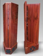
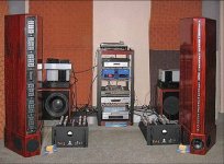
"Immediately apparent and most striking to anyone encountering the V60 for the first time, is its sculpture-like appearance, a 68” (173 cm) tall, open-baffle swept wing with an array of mid and treble planar panels standing on an integral triangular base housing its three 6.5” (16,5 cm) midbass woofers. With its slotted waveguide in place there is little to indicate this is a speaker system.
Speaking of our patent-pending waveguide, the mid/treble ribbon array is diffraction-slot loaded towards the front for 180 degree dispersion full-range, making the V60 a sit-and-enjoy anywhere reproducer.
Two distinct sounds are available: very broad dispersion with extraordinarily smooth mids and trebles (waveguide on), and a narrower, more concentrated soundfield with a very forward and tactile soundstage (waveguide off). Owners are encouraged to try it both ways and see which presentation suits them.
While the three woofers reside in a sealed enclosed (with a cutout nesting the easily-bypassed outboard passive crossover box, standard), the midrange rear wave fires into a reverse horn internally damped by a user-adjustable foam wedge, intended to kill reflections inside the horn from causing the horn-throat colorations collectively known as the Megaphone Effect. The wedge can be moved forward for quasi-sealed back operation, or rearwards away from the panels for partial or full dipole use depending on listening environment and personal preference. The rear wave path length is sufficiently long to eliminate cancellations from the Dipole Effect, a major source of nonlinearities in many open-baffle speakers. By folding its wings back the V60 achieves a front footprint of only 7” (17,5 cm) opening to a 22” (56 cm) rear.
Lowbass has been intentionally removed from the main column to cut down on surface-born modulation of the extremely low-mass (900 mg) planar mids exclusive to VMPS. Trebles are handled by the 20 mg moving-mass G3 ribbon tweeter. Sensitivity is high: 100 dB/1W/1m for the tweeter, 95 dB for the mids, and 94 dB for the woofers, allowing even small amplifiers to power the system to good levels. Output is very high (over 110 dB SPL at 3 m with a 100 W amplifier before clipping) and dynamics are explosive. The speaker fills the room with sound like few two-channel systems ever have, and is comfortable both in small or large listening rooms, close to side and back walls, or far away from them.
Accompanying the main columns is our new woofer, the Very Solid Sub (VSS) with a new high-acceleration 15” (38 cm) driver, 15” (38 cm) slot-loaded bottom passive radiator, and built-in 1000 W amp with electronic crossover and single-band parametric EQ which allows the user to notch out the floor-to-ceiling room mode (71 Hz with an 8ft ceiling). Indeed the system crossover is situated around 70 Hz to permit anyone with a good sub to eliminate this otherwise-intractable “room bloom” simply by moving the hinge frequency slightly lower. "
PICTURE OF RM_V60 WITH AND WITHOUT WAVEGUIDE
Attachments
Tom Danley said:Hi
It is true that you need a spherical wavefront to drive a conical corn without HOM’s. There are a few 1 inch drivers that can do this well up to about 60 –70 degrees, like a BMS 4550 and others of that geometry. Also, several 18 sound compression drivers are very good. At least one 1.4 inch drivers can on narrower horns.
You can see the real problem if you plot out the path lengths in the phase plug, they generally produce a converging wave front at summation.
The up side is, a conical horn if driven properly has (down to some size angle relationship) constant directivity and truly emulates a patch of spherical radiation.
Best,
Tom
Hi Tom
This does not sit well with me as the usual design of a compresion driver is intended to yield a flat wavefront at the throat aperature not a sperical one. It appears to me that a spherical one from an inverted dome would not be possible - the path length differences are too great. What data do you have to show that the wavefronts in these drivers are indeed spherical or evn close to being spherical - its not easy to measure this.
As someone else suggested, ALL waveguides are conical at larger radi just as ALL wavefronts are spherical at larger radi - not matter how they start out. Thus even though an OS appears to differ from a cone only at the throat - and this is indeed true - it is exactly at the throat that it matters the most. Hence what appears to be a small difference is in fact a huge difference.
I have looked at waveguides for ribbons. Anyone can call their devices CD - you have to prove it with data (or is that too much to ask?!)
The bulk of the remainder of the posts on ribbons is more marketing than science. There is no science for me to comment on or I would do so.
"We find the sound of the "revoiced" CD speakers done so far to be punchier and clearer, with no sacrifice of extension. A felicitous byproduct of CD technology, this change should please everyone who tries it."
Who can argue with that!!! (Since it doesn't actually say anything.)
Now that I am in Bangkok, and have access to my data I will post here the actual measurements of the ESP15. These are unretouched 1/3 octave averaged responses with all the gremlins present (like the notch at about 700 Hz from the woofers rim resonance).
These are exceptional responses which have not been equaled in any of the competition that we have measured (and no I haven't measured eveything and don't intend to). The solid black line shows the ULF (Ultra Low Frequency) sub response for this system.
Attachments
jzagaja said:Dear Earl,
Can you post Summa's CSD? (or provide wave/pcm file of the impulse response). Does below time domain data still valid for ESP15?
CSD is not something that I can readily do right now, its in the works.
The impulse that you show is for the Summas as taken back in the US some time ago. It is representative of current production but not exactly the same. You can see that the CSD would have a fairly steep drop since the impulse decays quite rapidly.
There is no real standard to CSD and different means yield different results. This is dangerous since it makes comparisons difficult to impossible.
What do you mean by no standard for CSD? Mathematics behind it or measuring environment?
What about MLLSA (standard) and ARTA - they are widely used everywhere and pretty similar. Just provide impulse response file and everybody with their favourite app. can read it and process.
Manger and RAAL for example are giving all the data - also their electrical playback response. Think about it.
jzagaja said:What do you mean by no standard for CSD? Mathematics behind it or measuring environment?
What about MLLSA (standard) and ARTA - they are widely used everywhere and pretty similar. Just provide impulse response file and everybody with their favourite app. can read it and process.
Manger and RAAL for example are giving all the data - also their electrical playback response. Think about it.
These are "widely used" but not "standards".
What format of impulse do you want - a one channel wave file is no problem? I have no problem supplying this, but I do have a real problem with believing that this tells the whole story. What about all the off-axis impulses. Do Manger and others supply those? I have a real problem with the idea that a single spatial impulse, especially the axial one, has a significant importance. It shows us a glimpse of what is going on, not the whole picture. I am always leery about supplying data that can be misunderstood and/or misconstrued.
I prefer to supply what I feel gives us the most significant view of reality. There are some things that you can see more readily in CSD (waterfalls), but nothing that isn't already visible in the impulse response, but there are many more that you cannot see in a single point measurement. CSD is just another way of looking at the impulse response.
The format can be: dbl, pcm, wav with specified sample rate, bits etc.
First of all I would like to compare briefly Summa with other horns. Off-axis impulses are obvious but ok. manufactures don't want or are too lazy publishing such data. With Manger it is easy because you can rent it for one month without extra cost and MSW was measured several times in many newspapers and AES papers (used in R&D). It would be fine if you can look on its CSD and tell me if you see a non terminated wave or reflections. It has beautiful brick wall even below 1kHz.
I know how microphone position affects CSD because I was practising it with my Jordan JXR6.
Attachments
jzagaja said:The format can be: dbl, pcm, wav with specified sample rate, bits etc.
First of all I would like to compare briefly Summa with other horns. Off-axis impulses are obvious but ok. manufactures don't want or are too lazy publishing such data. With Manger it is easy because you can rent it for one month without extra cost and MSW was measured several times in many newspapers and AES papers (used in R&D). It would be fine if you can look on its CSD and tell me if you see a non terminated wave or reflections. It has beautiful brick wall even below 1kHz.
I know how microphone position affects CSD because I was practising it with my Jordan JXR6.
I don't follow your discussion here. What does "Off-axis impulses are obvious but ok." mean?
Manufactures don't publish this data because its usually so bad. they prefer to publish what looks good no matter how meaningless it is - like axial frequency response, or 2nd and 3rd order THD.
When talking about "comparisons" of the Summa "waveguide" with other "horns" we must include directional considerations or the comparison is meaningless.
I will post a wav file of the ESP15 impulse response at 22.5 degrees as this is where it has its best response.
- Home
- Loudspeakers
- Multi-Way
- Geddes on Waveguides