phase linearizion of an LR24 at 1200Hz, and a closed box at 100Hz with bessel Q
(no other phase EQ used)
That fits quite well with the theory, which tends to indicate this speaker is very well behaved and filtered (as expected)
Hi Earl,
Post above states, that Abbey speakers are equipped with 24dB/oct, two-way crossover.
On the other hand, one of your happy users bought the kit in 2009.
GedLee Abbey 12 Loudspeaker Kit Immediately appealing with lifelike dynamics and great clarity. Article By Mike Galusha
He claims, "...Crossover: 2nd order passive, frequency not specified but approximately 1200Hz. Multiple LCR networks for the tweeter..."
Has the crossover changed?. Could you please verify what the correct crossover is?. Is there an RC high-pass lift for the tweeter?.
Best Regards,
Bohdan
The point here is that the "passive circuits" are whatever are necessary to yield the correct response. Call it whatever you want. It works and that's what matters. The computer algorithms don't know "24 dB/oct" or "third order", or "Linkwitz-Riley". Those concepts are entirely obsolete. What counts is what works.
What counts is the resulting acoustical slopes, and the fact that their amplitudes are complementary (L-R amplitude slopes being the most simple form of that) and their phase shifts are coherent (same phase shifts) throughout the crossover range.
The passive or active electrical crossover is just a mean to achieve that when coupled with the natural behavior of the drivers themselves.
The passive or active electrical crossover is just a mean to achieve that when coupled with the natural behavior of the drivers themselves.
What counts is the way the HP and LP acoustical subsystem responses add together in the far field both on and off axis. What the slopes and phases and amplitudes are is just a means to an end. I can plot what they are, but I don't look for anything in particular in the details, just the result.
")
I think we agree
other forms of complementary amplitude slopes (and coherent in phase) such as Horbach-Keele for example will give same on axis responses, but different ones off axis.
I am not sure that is possible. No electrical modification could change the response along one axis and Not change it along another axis. How would that be possible? Only an acoustical change could do that, right?
I am not sure that is possible. No electrical modification could change the response along one axis and Not change it along another axis. How would that be possible? Only an acoustical change could do that, right?
The on-axis (and time aligned) summation of two drivers of any complementary in amplitude and coherent in phase acoustical crossover should give the same response.
But as you move off-axis the summation will of course not be perfect anymore: distance between drivers will cause phase shifts, and differences in directivity behavior between drivers will cause amplitude differences. So the summed result will not be complementary in amplitude and coherent in phase anymore. In this situation different initial slopes, while still complementary on-axis, will give different results.
Horbach-Keele crossovers are an example of how this phenomenon can be taken into account for a WMTMW arrangement.
Stochastic interleave crossovers (pages 20 to 22) are another interesting possibility (scattering of anomalies), as CopperTop already pointed out somewhere on these forums.
I think that if one excludes the Hawksford proposal that what I am saying is probably true. It is certainly true if the phase is not a factor, but there might be cases where the phase changes could alter the situation.
The stochastic interleave might also be a situation that falls under what I am saying, its not clear. The amplitude response on all axes are changing, its not that one axis does not change while the others do. To me, the issue is: could one electrically change other axes responses whille leaving one stationary. I am not convinced that this is possible and your examples don't prove that it can.
The stochastic interleave might also be a situation that falls under what I am saying, its not clear. The amplitude response on all axes are changing, its not that one axis does not change while the others do. To me, the issue is: could one electrically change other axes responses whille leaving one stationary. I am not convinced that this is possible and your examples don't prove that it can.
The more I think about this the more convinced I am that one could never fix the response along one axis and change any other axis without changing the original one - with just electronics. I just do not see how this could happen. Changing one axis has to change all the others as well. Now finding the best compromise for this situation is what making a crossover is all about.
Hi Earl,
Sorry for the mishap yesterday. The system did not allow me to upload the attachment, so I removed the message. Hopefully, it’ll be OK now.
I have attached a paper, visualizing my line of thoughts, so perhaps you could refer to the paper while reading the reminder of this post.
Figure 1 – Shows the original woofer and tweeter drivers – from manufacturer’s specs. I do not know, if the tweeter’s data was taken with a HP filter.
Figure 2 – Reconstructed woofer and tweeter. Phase is generated from SPL via Hilbert-Bode Transform. Please note, that woofer is installed in a sealed box – as indicated by the asymptotic SPL (-12dB/oct), going towards lowest frequencies.
Figure 3 – Given the information from the previous posts, I have re-constructed one possible version of Abbey’s crossover. I have no idea if this is correct, and I am only showing one LRC network across tweeter. My understanding is, that there are 3 such networks.
This figure also contains minimum-phase response of the whole system.
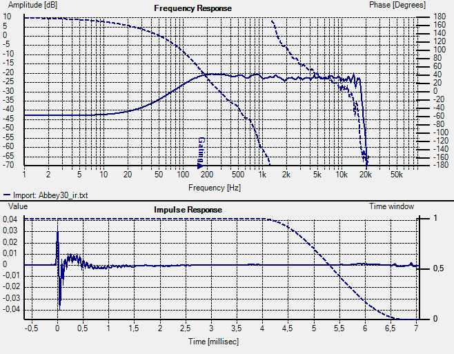
Figure 4 - IR of Abbey and SPL + Phase response. This was obtained from your file Abbey30_ir.txt using SoundEasy software. Please note remarkable similarity in phase response between measured and modelled. All phase transitions are in correct places in both: Figure 3 and Figure 4.
Figure 5 - IR of Abbey and SPL + Phase response from HolmImpulse. Setup parameters are shown as well. Please note remarkable similarity in phase response between measured and modelled. All phase transitions are in correct placed in both: Figure 3 and Figure 4.
Figure 6 – Pos’s measured tweeter phase response.
The goal of this whole exercise was to correctly determine phase response of the Abbey. It should be simple and easy to do. Knowing the phase response of the measurement chain would also help.
But all the above may turn out to be just a fantasy (and I would not be surprised if it did). Without your input I am not able to progress any further with this issue.
Best Regards,
Bohdan
Sorry for the mishap yesterday. The system did not allow me to upload the attachment, so I removed the message. Hopefully, it’ll be OK now.
I have attached a paper, visualizing my line of thoughts, so perhaps you could refer to the paper while reading the reminder of this post.
Figure 1 – Shows the original woofer and tweeter drivers – from manufacturer’s specs. I do not know, if the tweeter’s data was taken with a HP filter.
Figure 2 – Reconstructed woofer and tweeter. Phase is generated from SPL via Hilbert-Bode Transform. Please note, that woofer is installed in a sealed box – as indicated by the asymptotic SPL (-12dB/oct), going towards lowest frequencies.
Figure 3 – Given the information from the previous posts, I have re-constructed one possible version of Abbey’s crossover. I have no idea if this is correct, and I am only showing one LRC network across tweeter. My understanding is, that there are 3 such networks.
This figure also contains minimum-phase response of the whole system.
Figure 4 - IR of Abbey and SPL + Phase response. This was obtained from your file Abbey30_ir.txt using SoundEasy software. Please note remarkable similarity in phase response between measured and modelled. All phase transitions are in correct places in both: Figure 3 and Figure 4.
Figure 5 - IR of Abbey and SPL + Phase response from HolmImpulse. Setup parameters are shown as well. Please note remarkable similarity in phase response between measured and modelled. All phase transitions are in correct placed in both: Figure 3 and Figure 4.
Figure 6 – Pos’s measured tweeter phase response.
The goal of this whole exercise was to correctly determine phase response of the Abbey. It should be simple and easy to do. Knowing the phase response of the measurement chain would also help.
But all the above may turn out to be just a fantasy (and I would not be surprised if it did). Without your input I am not able to progress any further with this issue.
Best Regards,
Bohdan
Attachments
Ok, I understand the plots, but I don;t understand "Without your input I am not able to progress any further with this issue." You have the phase - its in the Holm data that I posted. I don't understand what is missing.
I will say this however, the DE250 data that you show is for an entirely different waveguide than mine and the data is completely different than mine. Hence any similarity in your reconstruction is likely a pure coincidence or "just a fantasy". (Or the fact that it is a minimum phase system so the phase ends up correct for the same end result no matter how you get there.) I don't know which. I never look at the phase so there is not much that I can add.
I will say this however, the DE250 data that you show is for an entirely different waveguide than mine and the data is completely different than mine. Hence any similarity in your reconstruction is likely a pure coincidence or "just a fantasy". (Or the fact that it is a minimum phase system so the phase ends up correct for the same end result no matter how you get there.) I don't know which. I never look at the phase so there is not much that I can add.
Heh, I think Earl never felt that phase was important. With only my school education background, I would have thought the same. But ever since I got into the human interface/interaction of control systems, I felt that phase was a very important factor for the appropriate feel of controls, a pretty involving design effort.
I think it would be interesting to take an Abby, and do a linearized phase version, and listen to the difference.
I think it would be interesting to take an Abby, and do a linearized phase version, and listen to the difference.
Last edited:
I think that if one excludes the Hawksford proposal that what I am saying is probably true. It is certainly true if the phase is not a factor, but there might be cases where the phase changes could alter the situation.
The stochastic interleave might also be a situation that falls under what I am saying, its not clear. The amplitude response on all axes are changing, its not that one axis does not change while the others do. To me, the issue is: could one electrically change other axes responses whille leaving one stationary. I am not convinced that this is possible and your examples don't prove that it can.
So you are implying that any complementary slope on-axis will give the same results off-axis?
This would be true if the two drivers were located at the exact same point and had the same polar response at (and around) the crossover point, so that the summation would be on phase everywhere (some coaxial drivers might qualify maybe, or synergy horns).
Horbarch-Keele crossover is a special case for WMTMW speakers and takes into account the phase shifts and associated consequence on amplitude summation to control vertical directivity.
Figure 6 – Pos’s measured tweeter phase response.
This is the response of the whole system, from the IR Earl posted.
I did reverse polarity to get the first peak positive (and have the phase shifts in the right direction up high).
I also applied windowing to the impulse in HOLM, so that the response in the lows looks smoother and shorter than it should.
I chose the impulse offset so that the phase response reaches 0° around 10khz. Response above 10khz does not look to be minimum phase anyway (due heavy diaphragm breakups I suppose), so I let the phase alone up there.
So here choosing this offset I am basically "hiding" the low pass behavior of the compression driver (as well as amplification and measurement systems), because showing it would not have a lot of interest.
Of course any other offset or phase polarity could give a different view of the phase that would be equally "true", so it is just a matter of choosing the one that suits your needs.
The one I chose let you see the theoretical behavior one would expect from that speaker (24dB/oct acoustical crossover at 1200Hz), and is easier to analyze, or correct using rephase for example.
Last edited:
I don't think the Abbey would benefit that much: the (acoustical) crossover point is already quite high in frequency (1200Hz) to get major audible gains, and there is not real crossover point with the sub per se.I think it would be interesting to take an Abby, and do a linearized phase version, and listen to the difference.
Heh, I think Earl never felt that phase was important. With only my school education background, I would have thought the same. But ever since I got into the human interface/interaction of control systems, I felt that phase was a very important factor for the appropriate feel of controls, a pretty involving design effort.
I think it would be interesting to take an Abby, and do a linearized phase version, and listen to the difference.
Your experiences do not show that phase is audible.
You have to understand that I retain phase in all my calculations (through complex number calculations) - it is critical in crossover design - but I just do not understand what importance the phase of the end result has. No one has ever shown it to be audible.
Last edited:
So you are implying that any complementary slope on-axis will give the same results off-axis?
I am saying that it is not immediately obvious that changing the on axis response could be done without changing the off axis response as well. This would then imply that different means to the same on-axis response should all yield the same off axis response. I would have to think about this some more, its never come up before, and doesn't really have any significant implications so I am not sure.
By the way, you keep saying that the Abbey has a 1200 Hz crossover, but that is not true the way that I define it. The acoustical outputs of the two drivers are equal at about 900 Hz and that's what I call the "crossover frequency". You are basically guessing based on you analysis, but it cannot be correct because the filters are not the slopes that you say they are. The HP is electrically only first order, its definitely not 24 dB/Oct. even acoustically.
- Home
- Loudspeakers
- Multi-Way
- Geddes on Waveguides