I was wondering if anyone in this nearly 400 long thread had come across 'pre-made' waveguides in other uses, be it the Habitat lampshades, or ceramic tagine lids, cheap megaphone, odd shaped vases or table bases.
There are an almost endless amount of objects which at first glance look ok, but which curves, diameters and all manor of things are wrong.
Would love to know if anyone has seen anything lurking in the wild.
There are an almost endless amount of objects which at first glance look ok, but which curves, diameters and all manor of things are wrong.
Would love to know if anyone has seen anything lurking in the wild.
Below are pics of the first elliptical waveguide I did. Measurements are somewhere in the thread.Elliptical OSWG parameters:
- throat diameter
- coverage
- mouth diameter
- roundover radius
I did a sketch with 45/90 deg coverage and fixed 5cm roundover keeping the length and mouth diameter constant. Is this correct or make length varied and roundover as in Iwata, JMLC, Ferguson horns?
An externally hosted image should be here but it was not working when we last tested it.
An externally hosted image should be here but it was not working when we last tested it.
I'm particularly interested in a small EOSWG. By using constant 5cm roundover it looses CD in vertical plane (45 deg coverage).
Thats what happens with small. To me, the waveguide needs to go much lower in control to be effective. You need to look at the system and what its requirements are and then design the waveguide from that. What you are showing has a much too high HP function.
no wonder - mms together with compliance sets basically the resonant frequency of the driver....
If you want to demonstrate the *behavior of the horn* or are designing a contour IMO its best to take the driver out of the equation (as good as it gets).
Otherwise you may not know which behaviour is from the driver and which is from the contour used - a pity when swapping drivers....
There is an other issue I came across digging into all that compression driver details - given the horn must be seen to begin at the very beginning of the phase plug slits - and also given this compression driver uses a basically conical flare from this point to the exit - where the horn contour begins - well - any contour calculation is flawed to some extent.
Looking at the OS contour for example what we actually have here is kind a manta-ray in that the first "kink" is between the conical flare of the compression driver and the asymptotic conical contour of the OS itself....
Same problem for any other contour of course - less hassles when substituting a compression driver by planar's / AMT")
Michael
If you want to demonstrate the *behavior of the horn* or are designing a contour IMO its best to take the driver out of the equation (as good as it gets).
Otherwise you may not know which behaviour is from the driver and which is from the contour used - a pity when swapping drivers....
There is an other issue I came across digging into all that compression driver details - given the horn must be seen to begin at the very beginning of the phase plug slits - and also given this compression driver uses a basically conical flare from this point to the exit - where the horn contour begins - well - any contour calculation is flawed to some extent.
Looking at the OS contour for example what we actually have here is kind a manta-ray in that the first "kink" is between the conical flare of the compression driver and the asymptotic conical contour of the OS itself....
Same problem for any other contour of course - less hassles when substituting a compression driver by planar's / AMT
Michael
Last edited:
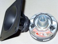
I took simplest horn driver like Tonsil GDWT (enclosed photo) its cross section. Drawn phase plug in AxiDriver and used standard motor for the domes. I can't detect any important difference in the midband.
There is no way that the third plot is correct. You need to doble check this.
This is a bug in Axidriver. Second phase plug member had open contour and error occurs "Invalid floating point operation". When you delete some points then it starts solving but the effect is null. So I understand that the loop must be closed - I need to hit the start point?
I took simplest horn driver like Tonsil GDWT (enclosed photo) its cross section. Drawn phase plug in AxiDriver and used standard motor for the domes. I can't detect any important difference in the midband.
What you try to demonstrate is the realization of what I mentioned - the contour basically should start out at the diaphragm - very clever find indeed
! - I haven't known of that driver's construction You really should try to do a horn if simus turn out any good...

Michael
So I understand that the loop must be closed - I need to hit the start point?
Yes, exactly
This is a bug in Axidriver. Second phase plug member had open contour and error occurs "Invalid floating point operation". When you delete some points then it starts solving but the effect is null. So I understand that the loop must be closed - I need to hit the start point?
Numerically in BEM, if there is a closed region that is exterior to the problem, then there will be a singularity in the solution. (Basically when this region has a resonance, it is singular.) There are ways arround this, but they have to be precisely coded to handle this situation - otherwise -> overflow.
One or two thought that come into mind following such a design attempt – not knowing how much weight in terms of sonics these may have – but anyway :
Looking at a simplified (one slit) version of your attempt, we can take a ring radiator – there are many out there.
Leaving aside diffraction alignment for a moment and looking at the cross area expansion rate of the horn only – we immediately see that we have to
- either make a kink in the contour where the inner phase plug ends
- or we have to extend the phase plug somewhere to the mouth of the horn
In compression drivers the kink in the (conical ?) contour is done at the place where the phase plug ends
Have a look at the picture of the cut TAD driver here:
http://www.diyaudio.com/forums/multi-way/103872-geddes-waveguides-76.html#post2049183
*If* you apply above philosophy for a multi slit design, things might get pretty complicated
Live can be more easy with planar's / AMT on horns....
Michael
Last edited:
That was my fault - due to number rounding one point had zero displacement, sorry
Can you explain what rounding this is? It might help me solve some issues using AxiDriver.
As can be seen, the sharp dip above 10KHz is not in the correct location, but does indicate something is going on as shown in the measurement. One thing to bear in mind when looking at these plots is that the diaphragm is assumed to be a rigid body, which is not the case in reality. Some papers by Mr. Klippel on Distributed Parameters explain this quite well.And comparison between original horn sim and manufacturer SPL plot.
That was my fault - due to number rounding one point had zero displacement, sorry
Thanks for sharing
Could you please also show on-axis normalised in comparison ?
Michael
- Home
- Loudspeakers
- Multi-Way
- Geddes on Waveguides