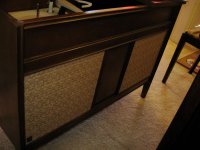
I picked up this console out of a house I was living in, figuring one day I would get to fix it up. Here we are! I can't find anything about this particular model.
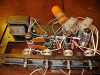
L to R - 12AX7, 6QA5A, 6QA5A, 6CA4
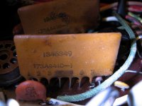
It was making a loud hum whenever I tried to turn it on, so I got new tubes for it. i know now that prob. all it needed was a recapping. I cannot figure out how to read this, tho:
I can't figure out what the total voltage needs to be. Also, it has 4 wires coming out of it, a black (the common ground), a red, a blue, and a green. All the capacitors I have seen only have a positive and negative coming out. Can anyone help me on this?
P.S. If you know anything about the console that would be great too!
An externally hosted image should be here but it was not working when we last tested it.
An externally hosted image should be here but it was not working when we last tested it.
An externally hosted image should be here but it was not working when we last tested it.
L to R - 12AX7, 6QA5A, 6QA5A, 6CA4
It was making a loud hum whenever I tried to turn it on, so I got new tubes for it. i know now that prob. all it needed was a recapping. I cannot figure out how to read this, tho:
An externally hosted image should be here but it was not working when we last tested it.
I can't figure out what the total voltage needs to be. Also, it has 4 wires coming out of it, a black (the common ground), a red, a blue, and a green. All the capacitors I have seen only have a positive and negative coming out. Can anyone help me on this?
P.S. If you know anything about the console that would be great too!
It's a triple capacitor in one housing - you'll need three to replace it. The caps have 250 V, (more at initial power-up) so must be 350 V rating or higher. The RC7100 isn't listed, but it's probably similar to RC4640 shown here: http://techpreservation.dyndns.org/schematics/General_Electric.htm
(You'll need the DjVBu browser plug-in from lizardtech.com)
(You'll need the DjVBu browser plug-in from lizardtech.com)
I picked up this console out of a house I was living in, figuring one day I would get to fix it up. Here we are! I can't find anything about this particular model.
Dude,
Whatever you tried to include in your initial post is not coming thru.
 If it's images, please provide URLs.
Notice that the RC4060A model Tom Bavis pointed you at has (IMO) yucky tone controls and uses a piezoelectric phono cartridge. If you use a CDP as the source and retain the OEM signal topology, less gain than a 12AX7 yields is needed. Replacing the 'X7 with a lower gain, but electrically similar, 12AY7 seems in order.
With very few exceptions, piezoelectric carts. literally scrub the HF info. out of record grooves.
 So, the OEM record playing stuff needs to be replaced.
You could do far, far, worse than switching to RH84 style circuitry.
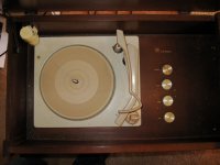
Replace the 1 MOhm resistors at the I/Ps with individual 100 KOhm log. taper Alpha Carbon controls from Mouser, to retain listening volume setting capability. ECC81 = 12AT7 and JJ (Slovakia) offers a decent version that's quite affordable.Sorry about the pics! I guess I have to attach them one at a time...the first one is the cabinet, then the record player, then the filter capacitor, and then the amp.
I ordered replacement caps the other day, so they should be in mid-week. I ordered a new needle as well, but you're saying that it's not worth it to keep it? I'm not a sooper audiophile guy...I just wanted to make it work.
That schematic looks very simliar to mine, but mine does not have a radio or a headphone jack. so here's another question: the switch on the record player turns the amp on. How do I need to wire it so the amp can be turned on with a switch? I am going to build a switchbox so I can use it for the record player and for an ipod or CD player. I've looked on the underside of the record player, but all I can see for a switch is a plate of metal that hits a little box that has wires coming out of it next to the motor. I have no idea what triggers it to switch off. Thanks for the help, and here's the pics.
Attachments
I ordered a new needle as well, but you're saying that it's not worth it to keep it? I'm not a sooper audiophile guy...I just wanted to make it work.
Sorry, that TT is a POS.
 It might be OK for 78s and 45 RPM "singles". No way should nice LPs go on that groove killer. Look carefully at the "business end" of the tone arm. Do you see the little lever sticking out sideways? That lever gets flipped to swap between the 3 mil 78 stylus and the microgroove stylus. You can bank on the tracking force being several grams.
 How do I need to wire it so the amp can be turned on with a switch?
Remember the previous remarks about simplification and elimination of the nasty tone controls. There are 4 chassis openings for controls. Put individual L/R volume controls in 2 of those openings. Put an on/off toggle switch in yet another of the openings. Put a rotary source selector switch in the 4th opening. Mouser stock # 105-14572 is a nice, inexpensive, choice for the source selector. Mount several sets of RCA jacks in new holes that you drill.
Search the Mouser site and you'll find Alpha Carbon volume controls and the toggle switch you need
I found a Hitachi HT-354 from a guy on CL with a Grado cartridge.
That's a significant improvement. However, you need a phono preamp that provides the gain and equalization the MM level Grado cart. requires to feed the console amp. Do you already own suitable electronics?
Yeah, I can handle all that.
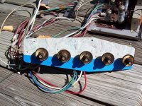
So, since I'm changing the pots (and moving them, bc the new TT won't go inside the console...I'm going to set up the power and selector switches and the new pots somewhere on the outside of the console)...all of them are dual pots. Why is that, and do I have to get dual pots to replace them? Also, take a look at that first pot on the left in the amp picture. On the amp, that's the "loudness" control. I cannot find a dual pot anywhere that had 6 poles on the bottom and the 2 extra ones those white and black wires are attached to. Do you see what I'm talking about? Do you have any idea what that does?
So, since I'm changing the pots (and moving them, bc the new TT won't go inside the console...I'm going to set up the power and selector switches and the new pots somewhere on the outside of the console)...all of them are dual pots. Why is that, and do I have to get dual pots to replace them? Also, take a look at that first pot on the left in the amp picture. On the amp, that's the "loudness" control. I cannot find a dual pot anywhere that had 6 poles on the bottom and the 2 extra ones those white and black wires are attached to. Do you see what I'm talking about? Do you have any idea what that does?
Keep all control functions near the electronics. Mount the new I/P RCA females where it's convenient. Run shielded "twinax" wire between the new RCA jacks and the source selector switch. Connect the shields only near the selector switch, to the chassis. The shields do not carry signal. That's why you use "twinax" wire.
There are 4 ganged, stereo, pots. (volume, balance, bass, and treble) in the unit. Refer to the model RC4640 schematic. Notice that the "extra" wires go to taps on the ganged volume control. Those taps are associated with a Fletcher/Munson bass boost at low listening levels.
Simplify, simplify, simplify! Sweep all of the nasty signal shaping circuitry away. A pair of mono, L/R, volume control pots. are the least expensive way to have control over both listening level and channel balance. Connect the wipers of the source selector switch to the new volume controls. The wipers of the new pots. connect to the 'X7 grids. Mouser stock # 31VJ501-F is what you need.
first thing I need to do is get it running!
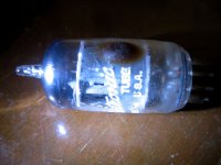
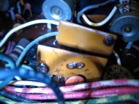
so i hooked up the new electrolytic capacitors, and nothing exploded! but then i noticed the 12ax7 wasn't lit. i'm going to attach some pics showing some damage (?) to the original 12ax7 and some damage (?) to the 2 big capacitors (?) that are next to it. does anyone know if that is a serious problem, and if so, what do i need to do? i've never seen these orange 7-pole things on any other amp, so i'm stumped. thanks in advance!
so i hooked up the new electrolytic capacitors, and nothing exploded!
but then i noticed the 12ax7 wasn't lit. i'm going to attach some pics showing some damage (?) to the original 12ax7 and some damage (?) to the 2 big capacitors (?) that are next to it. does anyone know if that is a serious problem, and if so, what do i need to do? i've never seen these orange 7-pole things on any other amp, so i'm stumped. thanks in advance!Attachments
Dude,
Those damaged parts, with multiple leads, are composites. Look at the schematic.
The circuit boards GE used appear to be low grade phenolic. Examine the Copper traces for damage.
JMO, you'll get the unit working faster if you get rid of all the signal shaping guano. The damaged composite parts are in the signal shaping stuff. Put the 100 KOhm pots. in and drive the unit with a CDP (perhaps a portable), during the shake down period.
Those damaged parts, with multiple leads, are composites.
Look at the schematic.The circuit boards GE used appear to be low grade phenolic. Examine the Copper traces for damage.
JMO, you'll get the unit working faster if you get rid of all the signal shaping guano. The damaged composite parts are in the signal shaping stuff.
Put the 100 KOhm pots. in and drive the unit with a CDP (perhaps a portable), during the shake down period. !
!so, what do i need to do to bypass the tone stuff?
Cr@p!
I just double checked the RC4640A schematic and the composite parts that are damaged are in the "real" part of the circuit, not the tone shaping stuff. Notice the dashed boxes around the parts intimately associated with the 12AX7 and 6AQ5s (1/channel). Those are the damaged composites. OUCH! Since you are probably forced into acquiring new, discrete, parts, make the topology change to RH84 style circuitry. The OEM PCB is of little use, unless a source for NOS composite parts exists. 
haha! yeah, someone on another site pointed that out to me...
and, they weren't damaged...it was just some wax that had built up on it...i felt like such a dumbace when i figured that out, believe me!
so, i've isolated the problem to the 12ax7 not lighting up. somehow, it's not getting power, so no sound. i need to get that working before i go and start taking the tone stuff out. any ideas on how to test that?
so, i've isolated the problem to the 12ax7 not lighting up. somehow, it's not getting power, so no sound. i need to get that working before i go and start taking the tone stuff out. any ideas on how to test that?
Examine the PCB for broken traces with a hand lens in strong light. Insert a new 'X7 to eliminate a dead tube. Jim McShane charges $10.75 for the very nice Sovtek 12AX7LPS.
J.
How's the project going. I just pulled the attached out of a GE Console left out for the trash man. It sounds pretty good with a cd source. I'm thinking about making a tube IPOD docking station.
The control panel includes a on\off selector switch, volume, bass, treble, and balance. I would like to replace all with a dual volume pot.
Any thoughts as to whether this amp is worth the effort?
Bruce
Attachments
- Status
- This old topic is closed. If you want to reopen this topic, contact a moderator using the "Report Post" button.
- Home
- Amplifiers
- Tubes / Valves
- GE Console RC 7100 A - need some help!