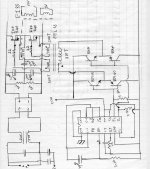
Hi I am building the attached shcematic to learn more about half bridge SMPS. Currently it is powered by 30Vac. The problem i am getting is that the BD139 and BD140 are heating up a lot. If i remove the high side mosfet everything cools down. Any help is appreciated. The IC is a TL494. Thanks.
Attachments
Things got worse
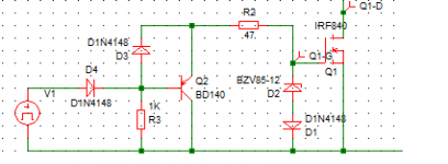
Hi i've adjusted the GDT turns ratio to 1:1. Now the high side mosfet is heating up and the BJT are still heating up. The high side mosfet gate resistor is heating up too.I measured the voltages across the GDT:
Primary +-10V square wave no ringing
Secondary +-10V square wave no ringing
Can anyone please help thanks
Good news up to now
I had an IRF540 handy which i've used and made the mods i mentionned. Everyting is working fine now i even applied 60Vac to the power section and everything remained cool. I'll get an IRF 840 and test from 30Vac up to 120Vac (2X 60 transformers in series) first before applying mains to the circuit.
I had an IRF540 handy which i've used and made the mods i mentionned. Everyting is working fine now i even applied 60Vac to the power section and everything remained cool. I'll get an IRF 840 and test from 30Vac up to 120Vac (2X 60 transformers in series) first before applying mains to the circuit.
Mains Test Ok but how to proceed next?
Placed an IRF840 in the circuit and went rom 30 to 210V isolated and finally 220V mains all went ok. No heating up at all. The EI-33 core is one i obtained from an ATX PSU and used it straight away. the unloaded voltage coming of the secondary is 200Volts on the transformer pins where normally 12V was expected. Would it be wise to load test the secondaries with a pair of 100W bulbs or would it better to implement rectification , common mode filter choke and Capacitor before testing?????
Thanks
Test Passed! 
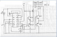
The circuit passed the 240V mains test with bulbs very well. I got 24V ac loaded with 2 100W bulbs in series (~48R cold resistance). or 12Vac + 12Vac between 12V pins and the wire which comes out out of most ATX SMPS. Everything remained cool, Mosfets, BJT's and IC. Next step am planing is loop control I still have the current sense transformer from the SMPS for overcurrent sensing to shut down the SMPS and I'll need to get an optocoupler for voltage regulation + TL431 + feedback circuit around the error amp. I'll post back as i move ahead with these time to study the annoying loop control now
The circuit passed the 240V mains test with bulbs very well. I got 24V ac loaded with 2 100W bulbs in series (~48R cold resistance). or 12Vac + 12Vac between 12V pins and the wire which comes out out of most ATX SMPS. Everything remained cool, Mosfets, BJT's and IC
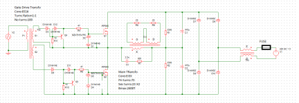
. Next step am planing is loop control I still have the current sense transformer from the SMPS for overcurrent sensing to shut down the SMPS and I'll need to get an optocoupler for voltage regulation + TL431 + feedback circuit around the error amp. I'll post back as i move ahead with these time to study the annoying loop control nowMain Core transformer
I am carrying on with the SMPS i prefered to coil my main transformer first. The turns in the transfromer were the ones it had out of a pc SMPS. Basically I am using an EI33 core for a 150W output +-35V to start simple. I will be driving the core at 2400G. The core x-section is 1.3cm square which gives me 73 turns primary and 23 turns secondary bifilar wound. Do these sound ok????
I am carrying on with the SMPS i prefered to coil my main transformer first. The turns in the transfromer were the ones it had out of a pc SMPS. Basically I am using an EI33 core for a 150W output +-35V to start simple. I will be driving the core at 2400G. The core x-section is 1.3cm square which gives me 73 turns primary and 23 turns secondary bifilar wound. Do these sound ok????
Blown Fuse and mosfet
Hi I've built the attached schematics. Everything worked very well up to 100V with a transformer powering the power section. But upon application of 220 Volts to the circuit the Fuse blew up immediately and the Mosfet got shorted GDS. No spikes or ringing noted with 100V applied to the circuit. I have even added a 0.22R in series with the mosfet but did not measure any waveform through the resistor. Any idea as to what could be tested or checked? the two 22ohm in the power circuit are 100W lamps i've used for testing.
Hi I've built the attached schematics. Everything worked very well up to 100V with a transformer powering the power section. But upon application of 220 Volts to the circuit the Fuse blew up immediately and the Mosfet got shorted GDS. No spikes or ringing noted with 100V applied to the circuit. I have even added a 0.22R in series with the mosfet but did not measure any waveform through the resistor. Any idea as to what could be tested or checked? the two 22ohm in the power circuit are 100W lamps i've used for testing.
Attachments
350V mosfets with a 220V half bridge is gambling I would be using 600V devices (IGBT's might be a better choice at this voltage).
Core saturation is one possibility Monitor the magnetising current as you increase the voltage, if spikes over an amp or so start to appear increase the switching frequency.
Core saturation is one possibility Monitor the magnetising current as you increase the voltage, if spikes over an amp or so start to appear increase the switching frequency.
Hi metalsculptor according to the specs of IRF840 they are 500V 8A devices. I know even the IRF730 rated 400V is used in 220V SMPS. I have rebuilt the gate drive circuitry after getting some help as they was a dealy to be suppressed in the fall time. Currently there is something strange that the lower mosfet gate signal is ok but the high side mosfet wave form is good but it is offset by 10V measured from GS. Attached is the new GDT.
Attachments
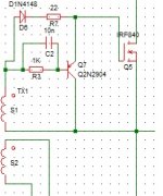
Hi metalsculptor according to the specs of IRF840 they are 500V 8A devices. I know even the IRF730 rated 400V is used in 220V SMPS. I have rebuilt the gate drive circuitry after getting some help as they was a dealy to be suppressed in the fall time. Currently there is something strange that the lower mosfet gate signal is ok but the high side mosfet wave form is good but it is offset by 10V measured from GS. Attached is the new GDT.
Any plans to show Gate signal of mosfets? Output Of your GDT?
Hi metalsculptor according to the specs of IRF840 they are 500V 8A devices. I know even the IRF730 rated 400V is used in 220V SMPS. I have rebuilt the gate drive circuitry after getting some help as they was a dealy to be suppressed in the fall time. Currently there is something strange that the lower mosfet gate signal is ok but the high side mosfet wave form is good but it is offset by 10V measured from GS. Attached is the new GDT.
My eyes are getting old I read IRF340, 500V should be fine. The strange gate drive may be due to stray capacitance, is the high side gate drive strange at all input voltages?
- Status
- This old topic is closed. If you want to reopen this topic, contact a moderator using the "Report Post" button.
- Home
- Amplifiers
- Power Supplies
- GDT loading Question