for a meter face you can redimension the face plate using a program like power point, and it is quite easy to slip in a string of blue surface mount leds.
i am sorry that i can't supply a kit of parts -- but everything should be readily available almost anywhere on the planet.
i am sorry that i can't supply a kit of parts -- but everything should be readily available almost anywhere on the planet.
Do you mean VU Meters?
What exactly does this board do? confused.
jackinnj said:for a meter face you can redimension the face plate using a program like power point, and it is quite easy to slip in a string of blue surface mount leds.
i am sorry that i can't supply a kit of parts -- but everything should be readily available almost anywhere on the planet.
What exactly does this board do? confused.
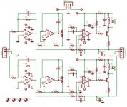
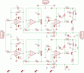
if you go back to the first post or so -- the board implements the attack and decay specified for a VU meter -- (but remember that the original standards were abandoned when modern recording equipment pushed the telco standards out of the way). It has broader dynamic range due to the use of two rail to rail opamps set up as a precision rectifier. The original circuit used a Linear Tech comparator -- but these might be a bit inconvenient for some folks to obtain so I used a garden variety bipolar unit. The circuit appeared in EDN a year ago or so, and I thought I would just make some boards for my own use and knock down the unit cost by doing a GB, offering them out at cost.
In deference to Linear Tech who came up with the idea I showed their parts in the schematic.
I've used another dual comparator -- the LM339 -- the LT1011 is a single, bipolar comparator -- both can sense near ground potential.
I have also used other opamps -- but the LT1469 is very fast, low noise and very acurate (16 bits).
Remember that the point of the device is to change the attack and decay of a VU meter circuit in order to be useful.
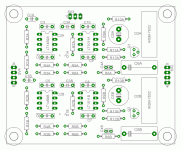
THrough a month of work , just finish a board (single-sided PCB replace with through hole 8-pin OPAMP sockets) use same components like an original introduced. However, my result is out of my thinking that is not work properly. So here seek your comment about this circuit whether anyone can succeed on building that with a good performance result ?
Hi CK, I did a quick hook up to the output of a of a CD player and and watched very small meter movement, the output was only .5 volt though. I need to wire it up correctly to see if it works correctly, I also need to figure out what my meters are and how to calibrate it as well. I'll try to get to it this later this week.
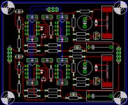
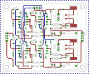
I made the circuit w/ Eagle, here is a revised .sch and board layout, keep us posted, thanks - Stan
I made the circuit w/ Eagle, here is a revised .sch and board layout, keep us posted, thanks - Stan
Attachments
The passage claimed the first stage gain factors is 6. In general speaking CD player can deliver 0.5-1v rms output for this circuit. So that it can be operated in a larger scale.
http://www.edn.com/contents/images/6280030.pdf
From the passage said IC2 which monitors the difference between the incoming signal's amplitude and the peak-detected output. What is the meaning to this statement ? What the function of the IC2 ?
If you can find what the problem of your case, please update to me. Later, I will try to make one of this prototype.
SCH & PCB I am using Protel SE 99 , it really a good thing but eagle i can try. Can you post the PCB brd layout file here ?
ckwong99 said:The passage claimed the first stage gain factors is 6. In general speaking CD player can deliver 0.5-1v rms output for this circuit. So that it can be operated in a larger scale.
http://www.edn.com/contents/images/6280030.pdf
From the passage said IC2 which monitors the difference between the incoming signal's amplitude and the peak-detected output. What is the meaning to this statement ? What the function of the IC2 ?
If you can find what the problem of your case, please update to me. Later, I will try to make one of this prototype.
SCH & PCB I am using Protel SE 99 , it really a good thing but eagle i can try. Can you post the PCB brd layout file here ?
Here's the Eagle .brd file.
Attachments

Hi. Do you have a BOM that goes with the PCB design? Thanks...
Hi Sylvain, if you are referring to me instead of jackinnj sure I will post the BOM and latest .brd/.sch file when I get back home in about a week.
I recently reworked the board and had the same problem of no gain at the outputs. It would be great to have your eyes and brain on this to see where my problem is if you are interested.
Best - Stan
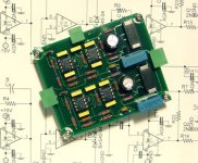
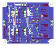
OK, here is the latest version of the board. I attached the BOM, Eagle files and pics of the board.
This schematic was created from the original EDN article Volume-Unit meter spans 60-dB dynamic range scroll down.
As mentioned before I had gain problems on output.
Hope this helps…
This schematic was created from the original EDN article Volume-Unit meter spans 60-dB dynamic range scroll down.
As mentioned before I had gain problems on output.
Hope this helps…
Attachments
- Status
- This old topic is closed. If you want to reopen this topic, contact a moderator using the "Report Post" button.
- Home
- Group Buys
- GB -- "VU Meter Amplifier" PCB