Hi Tea-Bag
As ZM and others recommended, I used .33 3 watt source resistors and a jumper for R11. I'll try the M2 on top. Lowthers are PM6As. Thanks again.
Thanks.
Hi Tea-Bag
As ZM and others recommended, I used .33 3 watt source resistors and a jumper for R11. I'll try the M2 on top. Lowthers are PM6As. Thanks again.
Alas I can't try this combination as Mouser slaps a ridiculous shipping fee if I order a couple of parts.
Alas I can't try this combination as Mouser slaps a ridiculous shipping fee if I order a couple of parts.
dewdrop,
Did you check Element14 Singapore? Last time I checked they had quite a few options for 0.33 Ohm 3 watt resistors.
Quick question on matched pairs of 2SK170 and 2SJ74.
Is Idss of 10.0 - 10.2 ok?
.
Yes, I would use 15R source resistors for JFET, instead of 10R.
Yes, I would use 15R source resistors for JFET, instead of 10R.
Thanks Tea-Bag, appreciated.
.
Excellent. It does have suprising bass. Do try on top.
Your speaker system sounds like mine, I use an OB Lowther.
Can you publish all resistor changes here for reference, now that it is working?
I want to edit the BOM if possible for these changes. It gets asked of me frequently.
Had the M2 on top for a few weeks. Good definition but darker and seemed rolled off on the top. Switched back to Aleph J on top and the outstanding female voices of Von Otter were back. Can build another Aleph J or an M2 with your mosfets. Not sure what to do. Do you have the B5 for crossover?
Hi Scranton,
I don't have any experience with the Aleph J. I know some people do really like it.
The M2 might appear rolled off because the transformer is not listed about 20k. I am not sure.
My ears are over 48 years old not, so I dont think I can hear about 14k last I checked. If so, its other parts of my body, not my ears.
I do use a B5 for a crossover with the open baffle. But In my basement system I just use plain M2.
In my experience, the Harris was a 'smoother' less shrill option that the Vishay IRFP9240. I believe the distortion curve problems in those were possibly the problem. Well, it's all I changed to resolve the issue.
The Fairchilds that were put into the original M2 from screenshots of the M2 papa amp, I tried those, they are good as well, but they are not really available at all anymore unfortunately. They were not as smooth as the Toshibas when I tried both in a F5 in the past, but then I found the Toshibas dry and sterile. An M2 I don't think is either of those things, Toshibas or not.
I still believe the M2 signature is dominated by the transformer. I was only able to change the sonic signature a little with cap tweaking or resistor changes.
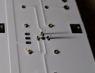
Query on Tea-bag M2 boards please... I am thinking about the grounding arrangement for my M2 which I have started building using Tea-bag's boards. Inspecting the boards I see that of the 6 mounting holes, one of the hole pads is connected via the thick ground trace from PSU-G via IN-G on the way. Thus, heatsink is likely to be connected to chassis at this point. I thought that the normal scheme was to connect chassis to ground (star or T off the +/- reservoir crossing) via RL-60 thermistor _only_ as per F5 manual PSU drawing. Should ground trace be broken near pad to avoid potential hum/noise? Or use an insulating mounting on that screw? Thanks.
Sorry, I meant ground is likely to be connected to chassis at this point.Thus, heatsink is likely to be connected to chassis at this point.
Sorry, I meant ground is likely to be connected to chassis at this point.
I tested a board this morning. If we take a default board which is v-scored into two channels, the inner rings next to "Left Channel" and "Right Channel" are grounded. This is meant to ground a potential shield covering of signal transformer if one is used. However, this is a round hole. The square holes are meant for chassis connection. Are you testing from the square holes?
Deeno,
You can refer to post #1 of this thread - Tea-Bag has a link for a bill of materials:
https://www.diyaudio.com/forums/gro...ds-120mm-ums-spacing-tea-bag.html#post4612640
You can refer to post #1 of this thread - Tea-Bag has a link for a bill of materials:
https://www.diyaudio.com/forums/gro...ds-120mm-ums-spacing-tea-bag.html#post4612640
Many thanx zman01!
You're welcome Deenoo, and have fun building this very nice sounding amplifier.
")
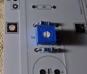
I didn't have much luck searching the thread so... I'm building up these boards, and the bournes potentiometer I sourced (from the BOM's recommendation) does not seem to correspond to the connections on the board.
- The pot has three connections. One of them lines up with a pad that is not connected, and one of the pads that is connected lines up with a missing connection on the pot.
- When you line up the pot with the pads, it appears to be a mirror image of the markings on the board.
Any clues as to what's going on?
Attachments
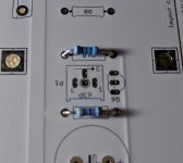
It doesn't matter if "1" and "3" doesn't line up with the same numbers on the board. Trimpots are not polarized. You can solder it in as you have it there.
Thanks! And I see now that the two center pads are connected, so it's moot which one the lead goes into.
Last edited:
- Status
- This old topic is closed. If you want to reopen this topic, contact a moderator using the "Report Post" button.
- Home
- Group Buys
- GB Pass M2 Clone Boards with 120mm UMS spacing by Tea-Bag