16 bit audio?Hello All.
I've got an interesting result that I can't explain - on the other PC.
With my powerful desktop workstation - no problem at all (post #918 above).
Exactly the same setup on the notebook - see attached.
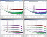
Very strange "garbage" at the output. The pictures show 1KHz spectrum at 0db, -20db, -30db and -50db. Input is fine - those spikes are produced at the output.
Any ideas?
Cheers,
Valery
I'm confused...
I've two RTX6001 at hand:
See image attached (RTX6001 where located at different places; quite likely not all settings where the same)
TIA
Ulli
I've two RTX6001 at hand:
- snr 0165 v1.10
- snr 0169 v1.16
See image attached (RTX6001 where located at different places; quite likely not all settings where the same)
0165 left ... 0165 right
0169 left ... 0169 right
0169 left ... 0169 right
- 0169 left channel shows much more mains hum compared to 0169 right channel
- 0169 noise floor varies much more than it does on 0165 (except for -20dB setting)
- at both devices, right channel has much more curly noise above 1 kHz than left channel
- 0169 noise floor does show low pass behaviour which is not seen at 0165
that was also the case with v1.10
TIA
Ulli
Attachments
This is always a problem with meters on the mains. That's why the Quant Asylum QA401 only has a USB power supply and no mains power supply.
I was thinking about mains, but the strange thing is that the desktop, also connected to mains, does not show any problem, but running with the laptop on batteries all these spikes appear throughout the whole audio band.
I'm confused...
sorry - different setups in use (0165 - in/out connected rather than open)
I'm confused...
sorry - different setups in use (0165 - in/out connected rather than open)
You will need a vertical shield btw generator and analyzer to eliminate the hum.
Jens, prepares a shield for this purpose but if you like to make some of these until these are available, the best way is a thin 1.4mm double side pcb (with cooper at the inside and outside).
I make some of these...and everything (hum, crosstalk btw L-R) has gone.
now with both devices having open input (pls ignore #923):
I've two RTX6001 at hand:
See image attached (RTX6001 where located at different places; quite likely not all settings where the same)
Ulli
I've two RTX6001 at hand:
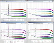
- snr 0165 v1.10
- snr 0169 v1.16
See image attached (RTX6001 where located at different places; quite likely not all settings where the same)
0165 left ... 0165 right
0169 left ... 0169 right
0169 left ... 0169 right
- left channel shows much more mains hum compared to right channel
- right channel has much more curly noise above 1 kHz than left channel
- 0169 left channel does show additional mains spurs
Ulli
Attachments
Last edited:
I noticed that the "mains hum" (in unbalanced operation) is quite sensible to the used cables and connectors. I had a set whose seat was not that firm and with those I had harmonics of the mains. With a better cable those harmonics were gone and the principal peak much lower.
You will need a vertical shield btw generator and analyzer to eliminate the hum.
Jens, prepares a shield for this purpose but if you like to make some of these until these are available, the best way is a thin 1.4mm double side pcb (with cooper at the inside and outside).
I make some of these...and everything (hum, crosstalk btw L-R) has gone.
Every (audio) device needs an iron metal case. Old rule...
@modmix - Are these captures with no any cables at inputs-outputs?
1) I see a lot of hum at the left channels, both units
2) the noise floor has strange response at the range.
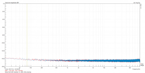
The attachment is capture of noise floor both of channel, without any cable on these. The knobs set 20dBV/20dBV for inputs-outputs, the Fs is 192K, the FFT is 131K and the Wnd is Hanning.
Everything is straight and clean, the hum from right channel has disappeard due vertical shields.
1) I see a lot of hum at the left channels, both units
2) the noise floor has strange response at the range.
The attachment is capture of noise floor both of channel, without any cable on these. The knobs set 20dBV/20dBV for inputs-outputs, the Fs is 192K, the FFT is 131K and the Wnd is Hanning.
Everything is straight and clean, the hum from right channel has disappeard due vertical shields.
Attachments
Yes.Are these captures with no any cables at inputs-outputs?
Looks like I should add some shields, too.Everything is straight and clean, the hum from right channel has disappeard due vertical shields.
Ulli
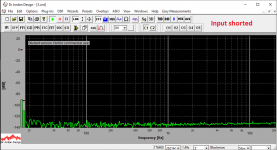
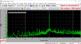
I did some more test runs. Pictures below (unbalanced input):
1) input is shorted;
2) input is connected to the output (short shielded cable) - no output signal;
3) same as above, but having 1KHz @ 0db at the output.
I tried different setups with regards to grounding - no change.
Still working perfectly (no artifacts at all) as soon as I connect the analyzer to the big desktop workstation...
Attachments
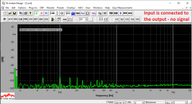
???2) input is connected to the output (short shielded cable) - no output signal;
Input of the analyzer is connected to the output of the analyzer's dac (analog loopback), but software generator is off - expecting to see a similar spectrum as picture 1 (noise only).
@vzaichenko
Please state also the attenuator settings, FFT window size and type of connection (single ended/balanced).
All switches are at the middle position (marks are looking up), single ended connection (pin 1 only), 262144 window.
I did some more test runs. Pictures below (unbalanced input):
1) input is shorted;
2) input is connected to the output (short shielded cable) - no output signal;
3) same as above, but having 1KHz @ 0db at the output.
I tried different setups with regards to grounding - no change.
Still working perfectly (no artifacts at all) as soon as I connect the analyzer to the big desktop workstation...
The first (1) is OK.
The second (2) has an impact of a little 50Hz hum, that generates a multiple spikes until 600Hz. I don't know if you have more hum sensitive unit or it is something from the measurement. The vertical axis is to dBV, if I see well.
The third (3) is not good and I don't know why, if your measurement setup was at the 0dBV for the output-input.
What is the dB of your gen? Probably, you tried with 0dB at the gen, else make a measurement with the same setup but with -3dB gen signal.
All switches are at the middle position (marks are looking up), single ended connection (pin 1 only), 262144 window.
What are you meaning, with this?
Perhaps, this is the cause of your problem.
You chosen the SE output (i.e you had 0.5Vrms output with 0dB gen signal) and how this connected to xlr?
Follow the diagram of attachment for this.
Attachments

Last edited:
- Status
- Not open for further replies.
- Home
- Group Buys
- GB for RTX6001 Audio Analyzer with AK5394A and AK4490