you know me, I want it to be black ") I am uncertain if there is any sound influence here.
I am uncertain if there is any sound influence here.
If I have not mentioned before, the transformer type and output FET dominated the sound of the parts I put into it, so I had trouble figuring out which parts were doing what.
I did try to use quality components in their. Includding caddock source R's as needed. I would recommend Bourns 3296y for 10R's, the 5K ones dont need to be as high end in my opinion.
The kit should have possibly an IRF and a semisouth option, as Source R's need to be a lot higher for iRF.
I am uncertain if there is any sound influence here.If I have not mentioned before, the transformer type and output FET dominated the sound of the parts I put into it, so I had trouble figuring out which parts were doing what.
I did try to use quality components in their. Includding caddock source R's as needed. I would recommend Bourns 3296y for 10R's, the 5K ones dont need to be as high end in my opinion.
The kit should have possibly an IRF and a semisouth option, as Source R's need to be a lot higher for iRF.
I have some 25V 1000uF Nichicon FWs and they fit perfectly with much room to spare. As 25V Panasonic FMs and FRs do.
Are the silmics that much bigger? I mean the working voltage should be at around 2,5V right? Shouldn t that allow for a much smaller cap? both in size and voltage rating?
Are the silmics that much bigger? I mean the working voltage should be at around 2,5V right? Shouldn t that allow for a much smaller cap? both in size and voltage rating?
Last edited:
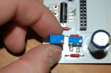
Using Kz instead of ELna Silmic II brings the kit price to $57 for a stereo pair. The Cinemag transformers will add $53. If turn out for them is really good, over 50 pieces, the price will drop to outstanding $51. Here is a pic of the mighty 3299 pot. Mack daddy of all pots.
Using the 3296 will save $2 off total kit price, as they are $.25 cheaper than 3299
Using the 3296 will save $2 off total kit price, as they are $.25 cheaper than 3299
Attachments
Last edited:
Talking about the part GB, I know that blue leds are prettier, but wouldn't a fast zener be a wiser choice? I mean noise-wise.
About the 1000uF caps, what voltage rating are we talking about?
I believe 25 or 35V is what I picked. I have a kit for PSU associated with the F5T GB if you are interested.
Nah I still have many parts from your previous F5T GB that are still waiting in their bag. I just wanted to have a look at a typical implementation of the white PSU boards. The photos on the blog are not very clear on that.
By the way, any chance that you can try a zenner on your test rigs and see if there is an improvement from the two blue leds?
By the way, any chance that you can try a zenner on your test rigs and see if there is an improvement from the two blue leds?
I m just insisting because I had a huge improvement by changing the blue/white led with a red non super bright one one on my DCB1's power indicator.
From a test here in diyaudio I remember that certain zeners where closer to plain leds and quiter than blue ones. And since we we have to use two blue ones, I guess the noise builds up
Here s the link to the test. If you check it, at some points zeners were almost 4 times quiter than blue leds.
http://www.diyaudio.com/forums/attachment.php?postid=417008&stamp=1087235682
PLease post pics of boards. IF you pull the pots, you must jumper that position. Pull the mosfets, and test just the bias section. Post pics first as we may be able to spot something. You can test continuity on the board with DMM any questionable location.
So I took another measurement on the board with the MOSFETs pulled. I could only get the bias at the gate pin on the board to read 0.5V with the pot at max. Something is not allowing the possible 5.5V available to get to the gates.
Either something is up with the Cinemags / daughter board or I have a resistor with a wrong value...UGH...
- Status
- This old topic is closed. If you want to reopen this topic, contact a moderator using the "Report Post" button.
- Home
- Group Buys
- GB for F6 Convertible Clone boards