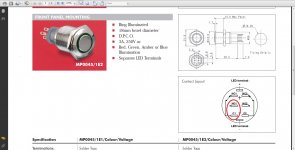
Looks like he used a Bulgin anti-vandal style switch. You can pick those up from Mouser or Digikey for around $20/ea. I think you need to use a seperate transformer & PCB to power the LED's and switch the relay for your power. Here is some information on the one I used for a headphone amp I built.
AMB Epsilon 24
AMB Epsilon 24
Horio, Your close.
It is an anti-vandal switch made by Bulgin. Mouser.com. 18mm
Model #MP0045/1E2
The model I use does not need a relay, it's rated at 250V AC /3A mains voltage. I took the power for the led ring from the F5 board's led output and added resistance in series to not fry the delicate LED.
Some of their switches are rated at 12V. and people mistakenly use that to provide power to the LED, (once). Non replaceable LED in the switch, Best to start off very low power and work up from there. I've used these switches before and they are great and supreme quality!
PDF file:
http://www.bulgin.co.uk/Products/Switches/documents/16mmStainlessSwitch.pdf
Mouser webpage link:
MP0045/1D2BL012 Bulgin Pushbutton Switches
Ron
Horio, Your close.
It is an anti-vandal switch made by Bulgin. Mouser.com. 18mm
Model #MP0045/1E2
The model I use does not need a relay, it's rated at 250V AC /3A mains voltage. I took the power for the led ring from the F5 board's led output and added resistance in series to not fry the delicate LED.
Some of their switches are rated at 12V. and people mistakenly use that to provide power to the LED, (once). Non replaceable LED in the switch, Best to start off very low power and work up from there. I've used these switches before and they are great and supreme quality!
PDF file:
http://www.bulgin.co.uk/Products/Switches/documents/16mmStainlessSwitch.pdf
Mouser webpage link:
MP0045/1D2BL012 Bulgin Pushbutton Switches
Ron
Ron,
Want to double check with you on something. You state that you are using the E2 version of the switch but you have linked the D2 version. The difference seems to be that the D2 version is a momentary switch versus the E2 which is a latching switch.
I'm a newbie to the terms momentary versus latching. Can anybody explain? Otherwise the switches look identical. FWIW, Ron (in a private e-mail) stated that the LED in this cool switch has a forward drop voltage of 3.3V and recommended a current of between 5-10mA (max 30mA), so you should definitely have a series resistor in line with the LED anode, or else the LED will be fried! The resistor calculator is right here:
Alan Parekh's Electronic Projects - LED Resistor Calculator
Thanks again Ron...
Anand.
My understanding (which is basic) is that a normally open momentary switch only makes the connection when you push down the button. As soon as it is released it goes back into its open position again. That is why I used that board I linked above in conjunction with a separate relay on the AC to the transformer.
Someone please correct me if I've got it wrong.
Someone please correct me if I've got it wrong.
Horio,
Thanks for the response. But why would you want a momentary switch then? Forgive me, I'm just used to the usual SPST, SPDT type switches. Basically you switch it on and it stays on until you switch it off. This is what the 'latching' switch sounds like to me.
Anand.
Thanks for the response. But why would you want a momentary switch then? Forgive me, I'm just used to the usual SPST, SPDT type switches. Basically you switch it on and it stays on until you switch it off. This is what the 'latching' switch sounds like to me.
Anand.
Anand,
So much for "Personal" email correspondence....")
You are correct, the type of switch SHOULD be a latching, not momentary type. If you read the PDF linked above you will see that the /1E2 model is the latching. Mousers weblink is incorrect. I found the correct one on their website and their link brought me to the page for which I provided a link. I should have read it better. Sorry.
I have used this switch on my Aikido preamp. Looks great.
As far as the mA value to start with, I stand by my opinion. Start low and work up from there.
Keep us informed of your progress.
Ron
So much for "Personal" email correspondence....
You are correct, the type of switch SHOULD be a latching, not momentary type. If you read the PDF linked above you will see that the /1E2 model is the latching. Mousers weblink is incorrect. I found the correct one on their website and their link brought me to the page for which I provided a link. I should have read it better. Sorry.
I have used this switch on my Aikido preamp. Looks great.
As far as the mA value to start with, I stand by my opinion. Start low and work up from there.
Keep us informed of your progress.
Ron
Attachments
Renron,
Where did you source the power switch on your F5 from - would really good on an amp I'm building (not a F5 unfortunately).
Thanks,
Mark
Check out Farnell part number 133-2000
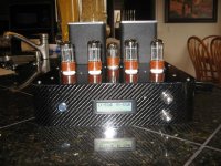
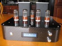
Wow. You are an artisan sir! Care to tell us where your attenuator is from? Very, very cool. I've ordered the switch btw, and I will start with a high valued resistor in series to limit the current. Don't want to fry a $14 switch!
Anand.
Thank you for the compliments, my projects come out well enough but I'm damn slow. That preamp took me 2 1/2 years to build. Most of that was learning about how glowing bottles work. Actual build time was about 3 weeks spare time.
I bought the attenuator from a listing on this website. There is a LONG series of posts where we (myself and others who bought this attenuator) discuss the problems we've had, and the lack of resolution from the seller. So, I'd rather keep it to myself, it does work as intended, it does have a remote function, but the relays "click" when the volume level is changed. It is very annoying to have it click, other wise it's a perfect build. IMO.
nothing's perfect, but it came out how I wanted it to look.Glad to hear you found the latching switch. They are built very, very well and beautiful to look at. Keep us informed with your progress.
Ron
Last edited:
Thank you for the compliments, my projects come out well enough but I'm damn slow. That preamp took me 2 1/2 years to build. Most of that was learning about how glowing bottles work. Actual build time was about 3 weeks spare time.
I bought the attenuator from a listing on this website. There is a LONG series of posts where we (myself and others who bought this attenuator) discuss the problems we've had, and the lack of resolution from the seller. So, I'd rather keep it to myself, it does work as intended, it does have a remote function, but the relays "click" when the volume level is changed. It is very annoying to have it click, other wise it's a perfect build. IMO.
Glad to hear you found the latching switch. They are built very, very well and beautiful to look at. Keep us informed with your progress.
Ron
Yup. Here is the correct link to the switch:
MP0045/1E2BL012 Bulgin Pushbutton Switches
Anand.
Anand,
Here is how I wired up my switch. Safe and sure.
Remember, IEC to fuse------> Switch---------> transformer(s)
Ron
PS. We have had several PMs as well, I needed to upload a photo and I don't know how to do that in a PM. I have no website presence.
Here is how I wired up my switch. Safe and sure.
Remember, IEC to fuse------> Switch---------> transformer(s)
Ron
PS. We have had several PMs as well, I needed to upload a photo and I don't know how to do that in a PM. I have no website presence.
Attachments
Last edited:
Hello everybody,
I can't stay away from this F5 amp more longer ! But I can't find the right PCB : Peter Daniel's PCBs are far too tiny, and the last issue from cviller has some extra options that I won't use, so here is my question : am I allowed to use the first pcb cviller's layout for a personnal re-issue ? It can be found here, post n° 2100.
Thanks
Hi androuski,
I can't really recommend using the posted layout for manufactured pcb's but only because gerbers (files ready for sending to production facility) will produce a better result. But the files are perfectly find for home etching and doing small batch somewhere.
I have given the gerbers to diyaudio, and I believe variac has already gotten some produced. I will ask him for a status.
hi christian, i'm working on an F5 based on ur board design and the pdf u posted on ur F5 blog.
for psu on the pdf (first watt standard style), are the inductors compulsory?
it they are, what is the recommended value and what kind of inductor is good (air core/solid core)
thank you in advance.
almost forgot ... hats of for the board design, including the V2.
excellent job, thumbs up.
for psu on the pdf (first watt standard style), are the inductors compulsory?
it they are, what is the recommended value and what kind of inductor is good (air core/solid core)
thank you in advance.
almost forgot ... hats of for the board design, including the V2.
excellent job, thumbs up.
- Status
- This old topic is closed. If you want to reopen this topic, contact a moderator using the "Report Post" button.
- Home
- Group Buys
- Gb: F5 Pcb