I designed and built my current system during 2006, it is a WWMT with Scan-speak 21W8555-01 8" woofers, Accuton c2-6-78 midrange and Accuton c30-6-24 tweeter, height some 110cm. Due to other priorities i had to stop spending time on speaker design and thus remained some unfinished work on my speakers as of 2007.

Current set up in living-room, 5.3m wide and quite asymmetric, to the right there is another small room ;-)
A few of years ago i started to look into this matter of speaker design again, studied the publications on the subject (Toole, Griesinger, Johnston, diyaudio.com, etc) on design as well as sound reproduction and played with 6mm felt sheets to reduce the unwanted diffraction effects, not much improvement.
Last year just as a "just do it" step i took some absorption panel (cotton, shredded jeans, very difficult to cut), and quickly made something and put it on the speakers.
Some difference!, most striking was the timbre of voices, instruments, stayed much more constant across the room, also more involvement.

I got intrigued, and this spring re-assembled measurement rigs, made a turntable, and together with Arta and VituixCAD started to get experienced again in measuring and analysis. I decided to start basically all over again, be it with the assembled enclosure with drivers as a given. The passive crossover, and any physical adaptations for the edge diffraction, be it within the limitations of the front of the speaker, are to be engineered from scratch.
The objectives:
• Flat anechoic on-axis response, note: will require tilting the tweeter forward as baffle is tilted backwards.
• Smooth off-axis response & early reflections response and sound power & DI
• Distortion focus, be it with given drivers. Note: Filter choices can influence distortion.
• Spurious noises (already non-existent sofar, but the metal grilles are suspect)
• From my experience and listening preference:
This all gave me a starting point in my loudspeaker project, named:
GAYA2-Final: Finishing the unfinished after 15 years
As the name implies it is to finish what I started in 2005 and had to stop end of 2006, engineered to the current state of the art.
Key to being successful is the following: “Through measurements to knowledge” (door meten tot weten) , the quote of Heike Kamerlingh Onnes.
This principle is fundamental, therefore from the desktop research:
And when done to incorporate what currently is possible for room corrections in the currently well-developed digital dimension of sound reproduction. I already have purchased Uli’s Acourate Pro and Mitch’s Hang Loose Convolver for this aspect.
The start:
I learned the tools by exercising measurements, study forum and article/book publications and perform analyses to fully understand them, before beginning with the real thing.
To cut a long story short: See also the thread Tmuikku started: https://www.diyaudio.com/community/...sover-and-tilt-experiment.388389/post-7097857
The outcome , quite humbling, is first of all the absorbing matter did make a difference, but also I have to get my measurements correct and repeatedly consistent, including getting rid of some DC error / very low frequency rubbish and the floor and ceiling reflection to get a decent gate in msec. Last but not least, my current baffle-shape for midrange and tweeter needs serious improvement (no surprises there 😉)
So back to the drawing board.
And not to forget enough space around the speaker during measurements, which means temporarily re-arranging the living room, thus only possible when I am alone and having enough time. 😉
Current set up in living-room, 5.3m wide and quite asymmetric, to the right there is another small room ;-)
A few of years ago i started to look into this matter of speaker design again, studied the publications on the subject (Toole, Griesinger, Johnston, diyaudio.com, etc) on design as well as sound reproduction and played with 6mm felt sheets to reduce the unwanted diffraction effects, not much improvement.
Last year just as a "just do it" step i took some absorption panel (cotton, shredded jeans, very difficult to cut), and quickly made something and put it on the speakers.
Some difference!, most striking was the timbre of voices, instruments, stayed much more constant across the room, also more involvement.
I got intrigued, and this spring re-assembled measurement rigs, made a turntable, and together with Arta and VituixCAD started to get experienced again in measuring and analysis. I decided to start basically all over again, be it with the assembled enclosure with drivers as a given. The passive crossover, and any physical adaptations for the edge diffraction, be it within the limitations of the front of the speaker, are to be engineered from scratch.
The objectives:
• Flat anechoic on-axis response, note: will require tilting the tweeter forward as baffle is tilted backwards.
• Smooth off-axis response & early reflections response and sound power & DI
• Distortion focus, be it with given drivers. Note: Filter choices can influence distortion.
• Spurious noises (already non-existent sofar, but the metal grilles are suspect)
• From my experience and listening preference:
- Crossover frequencies: ~435 and ~3465 Hertz (based on the discrimination bands of our hearing, reduction of doppler effect distortion)
- Sound stage aka dimensionality,
- separation of the individual voices/instruments
- left-right & depth
- Mostly playing at lower levels (< 80 dB), occasionally also louder.
- Timbre constancy in room at various listening positions.
- Envelopment (being there sort of independent of the actual living room)
- Engagement, does the music make me engage, does it trigger emotions.
This all gave me a starting point in my loudspeaker project, named:
GAYA2-Final: Finishing the unfinished after 15 years
As the name implies it is to finish what I started in 2005 and had to stop end of 2006, engineered to the current state of the art.
Key to being successful is the following: “Through measurements to knowledge” (door meten tot weten) , the quote of Heike Kamerlingh Onnes.
This principle is fundamental, therefore from the desktop research:
- Arta, Limps and Steps for measurements and some of the analysis.
- Calibrated microphone
- VituixCAD for the crossover design and simulation, taking a holistic view on and off-axis and step performance.
- And very important: Listening test, not only to correlate sims with the reality, also to achieve my perception based objectives.
And when done to incorporate what currently is possible for room corrections in the currently well-developed digital dimension of sound reproduction. I already have purchased Uli’s Acourate Pro and Mitch’s Hang Loose Convolver for this aspect.
The start:
I learned the tools by exercising measurements, study forum and article/book publications and perform analyses to fully understand them, before beginning with the real thing.
To cut a long story short: See also the thread Tmuikku started: https://www.diyaudio.com/community/...sover-and-tilt-experiment.388389/post-7097857
The outcome , quite humbling, is first of all the absorbing matter did make a difference, but also I have to get my measurements correct and repeatedly consistent, including getting rid of some DC error / very low frequency rubbish and the floor and ceiling reflection to get a decent gate in msec. Last but not least, my current baffle-shape for midrange and tweeter needs serious improvement (no surprises there 😉)
So back to the drawing board.
And not to forget enough space around the speaker during measurements, which means temporarily re-arranging the living room, thus only possible when I am alone and having enough time. 😉

In order to understand the impact of the baffle on the midrange frequency response i did a quick test as shown in Tmuikku's thread (see above). I first focused on the on-axis response.
In 2 different sessions i made measurements, here combined in 1 graph:

Bottom 4 responses, measured on-axis at 1000mm from midrange baffle:
thick red dash C90-6-078-R--Bare01_deg0: the baffle without any mod's for midrange or tweeter, the "bare baffle".
thin violet dash C90-6-078-R--ECOabs-Wig01-V02_deg0: On both sides a wedge of the EcoAbs material (~ 10cm wide, 4 cm thick))
thin light green dash C90-6-078-R--ECOabs-JDI_deg0-TEST: The original JDI EcoAbs material
thin dark green dash C90-6-078-R--Flamex-Wig01_deg0-TEST: On both sids a wedge of Flamex (melamine foam) shape similar to the EcoAbs wedges.
Used Vituixcad IR2FR to generate the frequency Response, with settings:

Note: The little hump at 7.5msec is the remainder of the floor reflection as i use absorbing plates to reduce that.
Top 4 responses, in this session i aimed at developing an understanding of which edges are responsible for what part of the diffraction effects:
thick red dash C90-6-078-R-Bare-Hart-1000mm-20221027-96k-F2Resp-Floor-02: again the response with the bare baffle but with the tweeter wedges.
thin violet dash C90-6-078-R-WhiteAdapter-Hart-1000mm-20221027-96k-F2Resp-Floor-01: with 3mm thick carton a smooth baffle
thick green dash C90-6-078-R-WhiteAdapter-rounded-hole-Carton-Ridge-putty-top-Hart-1000mm-20221027-96k-F2Resp-Floor-0: with make shift add-ons for the bottom and top ridge. See attached picture:

blue-red combo the D1 is actually C90-6-078-R-WhiteAdapter-rounded-hole-Carton-Ridge-putty-top-Hart-905mm-20221027-96k-F2Resp-Floor-01: like last one but measured at 905mm distance.
The Vituixcad IR2FR setting used:

My take-away from this:
Smooth baffle, avoid sharp edges, the top edge had a strong impact on the dip around 1.8 kHz, absorbing material on baffle can help (but not so straightforward, the baffle behaviour remains present to an extent) , check on different measuring distances as i am dealing with interferences.
Question to address: how to take the tweeter part of the baffle into the equation.
In 2 different sessions i made measurements, here combined in 1 graph:
Bottom 4 responses, measured on-axis at 1000mm from midrange baffle:
thick red dash C90-6-078-R--Bare01_deg0: the baffle without any mod's for midrange or tweeter, the "bare baffle".
thin violet dash C90-6-078-R--ECOabs-Wig01-V02_deg0: On both sides a wedge of the EcoAbs material (~ 10cm wide, 4 cm thick))
thin light green dash C90-6-078-R--ECOabs-JDI_deg0-TEST: The original JDI EcoAbs material
thin dark green dash C90-6-078-R--Flamex-Wig01_deg0-TEST: On both sids a wedge of Flamex (melamine foam) shape similar to the EcoAbs wedges.
Used Vituixcad IR2FR to generate the frequency Response, with settings:
Note: The little hump at 7.5msec is the remainder of the floor reflection as i use absorbing plates to reduce that.
Top 4 responses, in this session i aimed at developing an understanding of which edges are responsible for what part of the diffraction effects:
thick red dash C90-6-078-R-Bare-Hart-1000mm-20221027-96k-F2Resp-Floor-02: again the response with the bare baffle but with the tweeter wedges.
thin violet dash C90-6-078-R-WhiteAdapter-Hart-1000mm-20221027-96k-F2Resp-Floor-01: with 3mm thick carton a smooth baffle
thick green dash C90-6-078-R-WhiteAdapter-rounded-hole-Carton-Ridge-putty-top-Hart-1000mm-20221027-96k-F2Resp-Floor-0: with make shift add-ons for the bottom and top ridge. See attached picture:
blue-red combo the D1 is actually C90-6-078-R-WhiteAdapter-rounded-hole-Carton-Ridge-putty-top-Hart-905mm-20221027-96k-F2Resp-Floor-01: like last one but measured at 905mm distance.
The Vituixcad IR2FR setting used:
My take-away from this:
Smooth baffle, avoid sharp edges, the top edge had a strong impact on the dip around 1.8 kHz, absorbing material on baffle can help (but not so straightforward, the baffle behaviour remains present to an extent) , check on different measuring distances as i am dealing with interferences.
Question to address: how to take the tweeter part of the baffle into the equation.
Last edited:
First looking back a bit. I tested with sound absorption material in order to get a smoother on and off-axis response. To cut a long story short: I stopped in that rabbit-hole (for now).
It showed both an behavior as if the baffle width was increased(longer path to diffraction edge) at frequencies between 500 – 2000 Hz approximately (increased output of 1-2dB), and some absorption from say 800Hz and up but diminishing above ~ 2kHz due to increase in beaming of driver. This apparent width increase did exaggerate the baffle behavior of initial bump and dip. It did smoothen the off-axis response though.
Note: for that purpose the ECO-Absorption material (shredded jeans etc) showed more absorption than flamex (melamine-foam).
So decision taken to alter the baffle around midrange and tweeter, basically adding material in order to get a smooth and flush baffle (current situation has quite a few steps/ridges). Also in the mean time I asked @augerpro (Brandon) to help in developing a waveguide for the Accuton C30-6-024 tweeter , in photo already with grille removed):

When that design arrived I already arranged a 3D filament printer, and in Draft mode created for initial testing a usable waveguide. ( i filled and sanded it a bit not shown )

Scanning through the posts on DIYAudio about waveguide mounting etc convinced me that the edge should be flush mounted.
So I made a baffle add-on in two pieces, one for midrange and one for tweeter part.
I cut and glued together some foamboard (a leftover form my Fine Art Printing shop), and then did cutout and for midrange some filler to provide a smooth edge.

The midrange is now recessed, thus need to figure out the shape of the edge around the midrange. I will remove the grille, if necessary, but for now I leave it as a protection).
In the mean time I did test to figure out how to minimize room influences on the measurements. (I have to do this in our living room, and at times I am alone and with enough time to setup , perform, and remove & restore 😉).

(note: last measurement got impacted by the tray in front I overlooked , so the midrange measurements need to be done again;-~)
Also I looked into the diffraction simulation with different tools (Vituixcad, Edge, Bagby excel) and finding some plausible correlation with measurements. This turned out to be another rabbit-hole, as my enclosure shape is simply not available in those tools (elliptical cross-section , floor-standing), with baffle width of 26.2cm but main width of enclosure being 32.8cm. And of course the not perfect frequency response behavior of the midrange in that crucial range.
Enough for quite some posts, but first the first round of test results with the tweeter waveguide.
The Accuton C30-6-024 flush mounted and with ECOAbs wedges left and right, versus the waveguide as depicted above:


Note I did not apply a short gate, and the flush mounted was measured with 48kHz sampling versus 96kHz for the other measurements. Both with distance of 1000mm from the front. So with the waveguide the tweeter itself is actually some 18mm further away.
In vertical direction I did moved the tweeter some 10cm up (so at 3m listening distance that would be 30cm) , the response is virtually identical.
I did not have time enough to set up the turntable for horizontal off-axis measurements, so I did only test at 30 degrees of axis:

Pretty clear that the beaming of the tweeter at increasing frequencies is less and more even with waveguide. Also that there is some anomality from 10kHz upwards and some dip at 3.3 kHz. Note: The breakup starting a little above 20kHz is something I want to reduce in the xo-filter, like Purifi has shown in one of their technical articles.
The anomalities may be because of the not-perfect alignment which I did by sight. Note that I did take care not to have a small gap between the tweeter faceplate and the waveguide throat. Perhaps something else as well?
It showed both an behavior as if the baffle width was increased(longer path to diffraction edge) at frequencies between 500 – 2000 Hz approximately (increased output of 1-2dB), and some absorption from say 800Hz and up but diminishing above ~ 2kHz due to increase in beaming of driver. This apparent width increase did exaggerate the baffle behavior of initial bump and dip. It did smoothen the off-axis response though.
Note: for that purpose the ECO-Absorption material (shredded jeans etc) showed more absorption than flamex (melamine-foam).
So decision taken to alter the baffle around midrange and tweeter, basically adding material in order to get a smooth and flush baffle (current situation has quite a few steps/ridges). Also in the mean time I asked @augerpro (Brandon) to help in developing a waveguide for the Accuton C30-6-024 tweeter , in photo already with grille removed):
When that design arrived I already arranged a 3D filament printer, and in Draft mode created for initial testing a usable waveguide. ( i filled and sanded it a bit not shown )
Scanning through the posts on DIYAudio about waveguide mounting etc convinced me that the edge should be flush mounted.
So I made a baffle add-on in two pieces, one for midrange and one for tweeter part.
I cut and glued together some foamboard (a leftover form my Fine Art Printing shop), and then did cutout and for midrange some filler to provide a smooth edge.
The midrange is now recessed, thus need to figure out the shape of the edge around the midrange. I will remove the grille, if necessary, but for now I leave it as a protection).
In the mean time I did test to figure out how to minimize room influences on the measurements. (I have to do this in our living room, and at times I am alone and with enough time to setup , perform, and remove & restore 😉).
(note: last measurement got impacted by the tray in front I overlooked , so the midrange measurements need to be done again;-~)
Also I looked into the diffraction simulation with different tools (Vituixcad, Edge, Bagby excel) and finding some plausible correlation with measurements. This turned out to be another rabbit-hole, as my enclosure shape is simply not available in those tools (elliptical cross-section , floor-standing), with baffle width of 26.2cm but main width of enclosure being 32.8cm. And of course the not perfect frequency response behavior of the midrange in that crucial range.
Enough for quite some posts, but first the first round of test results with the tweeter waveguide.
The Accuton C30-6-024 flush mounted and with ECOAbs wedges left and right, versus the waveguide as depicted above:
Note I did not apply a short gate, and the flush mounted was measured with 48kHz sampling versus 96kHz for the other measurements. Both with distance of 1000mm from the front. So with the waveguide the tweeter itself is actually some 18mm further away.
In vertical direction I did moved the tweeter some 10cm up (so at 3m listening distance that would be 30cm) , the response is virtually identical.
I did not have time enough to set up the turntable for horizontal off-axis measurements, so I did only test at 30 degrees of axis:
Pretty clear that the beaming of the tweeter at increasing frequencies is less and more even with waveguide. Also that there is some anomality from 10kHz upwards and some dip at 3.3 kHz. Note: The breakup starting a little above 20kHz is something I want to reduce in the xo-filter, like Purifi has shown in one of their technical articles.
The anomalities may be because of the not-perfect alignment which I did by sight. Note that I did take care not to have a small gap between the tweeter faceplate and the waveguide throat. Perhaps something else as well?
Last edited:
Thanks, would that also address the 3.3kHz dip?Tape around the edge of the waveguide so there isn't a gap, and remeasure.
Probably not, I've never had issue that low before.Thanks, would that also address the 3.3kHz dip?
Below 2 VituixCAD essays, the first one uses the data of 15 years ago. But then i used XSIM, however VituixCAD gives a somewhat different result. XSIM is one axis only so multiple axis responses not shown in one view.15 years! I love this perseverance, and the cabinet profile is very elegant.
Can I ask about the 21W crossover slopes? Are the woofers rolled off at the same frequency? Did you have to notch out the breakup peaks?
The second one is an essay to get aquainted with VituixCAD, and just some measurements some months ago, to see if i can get a filter where the woofers do not have to be in reverse polarity. It also shows the diffraction issue (big dip around 1700 Hz) with the midrange and the beaming diffferences between midrange and tweeter. Reason for me to focus on a waveguide for the tweeter and modification of baffle for the midrange to get a smoother response in the critical 700- 2500 Hz region.
My dream actually is to get the 8" Purifi woofers once having solved the issues with midrange and tweeter. (and a good midrange other than Accuton C90-6-724, still waiting for one from Purifi ;-)).
These 8" drivers should fit well physically and in the sealed box volume (27L), but as they have a higher spl, i will need to connect them in series, which will solve the issue of low impedance in the 150-200Hz range in current configuration. Or go active 2 channel one for bass one for midrange-tweeter combo.
Anyhow coming thursday i will do measurements on at least tweeter, now with well mounted waveguide including off-axis, and if time permits also midrange. with modifications to its baffle The first measurements with the waveguide were promising, but very limited, and the mounting was quick and dirty. So new waveguides made now with mounting flanges so it can be bolted on and properly aligned with cone. This also allows to place a thin shim to assure no air-gap in between wg and tweeter frontplate.
Hi, I like your plan.
You got great drivers and build a fantastic looking cabinet.
Then you made the first grave mistake with the baffle. It is (you sure know today) just a recipe for disaster. The second, even bigger fault was to build the x-over you made, as it can not work with this baffle.
A long time ago I visited a very recognized German author of speaker building books and free lance developer for the industry. He had a huge, squeaky clean lab with any tool one cold think of at that time. This visit set my perspective right, what I was as “speaker builder” and designer. I felt quite small and stupid. While he was building an x-over for our box project gone wrong (a kit, very good driver, well build 3-way cabinet, x-over made by an complete idiot) he told me some basic things I still remember today:
"It is very hard for an amateur to build a good 2-way.
It can be done, learning a lot about theory and spending a lot of time plus reasonable money.
You have to have educated, absolute hearing or measure. Best both.
You at least need a reference speaker to readjust your ears or you get used to wrong sound while tuning.
Something no one thinks of. A small monitor is fine. Visiting concerts helps a lot. Small venues, where you hear non amplified instruments and voices.
Last:
It is impossible for an amateur to construct a 3-way that stands an objective test."
Ok, today we have all the tools that, at that time, were unobtainable for you and me or not even invented, like computer simulations. While some may be a little outdated, there is still a lot of importance left.
If you think about going active for the woofer, why not go the whole way and make it active 3-way?
Why not build an improved baffle, maybe add an wave guide (it is not essential at all for this tweeter) and use your huge knowledge, just not with cab's n' coil's, but a DSP. Trust me, the cost to go from 2-way to 3-way active is nothing you will really notice. You can start with one side (you need the same gear as for 2-way stereo!) and stretch cost over time.
Last edited:
"think about going active for the woofer, why not go the whole way and make it active 3-way?"
Something like this
https://www.diyclassd.com/product/fusionamp-fa123/154
https://www.diyclassd.com/product/fusionamp-fa253/157
https://www.diyclassd.com/product/fusionamp-fa503/160
Last edited:
Then you made the first grave mistake with the baffle.
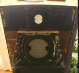
op, can you show us a picture of the original tre/mid baffle area
@ctrlx : It is shown in post 3. The measurements of xo with the dip was on this baffle with a 2cm thick absorbing material. At this moment making some changes to a new baffle prototype to see if the dip on-axis is minimised, and the off axis are well behaved. And on both sides of the tweeter a wedge of same material.
What i learned the past months that baffle diffraction effects increase with measuring distance, and from 1m onwards sort of stabilize. ( my yesteryear measurements were mostly on shorter distances, so useless today)
In essence i see the baffle as a type of waveguide, where you need to incorporate edge diffractions in the middle of the bandwidth and the enclosure shape 'behind' the baffle. The crossection of my enclosure is basically ellips shaped, with one end cut off for the baffle. The front baffle ia 26.2cm, and the max width of the enclosure is 32.8cm and in simulations it look like the 32.8cm width effects are also present. Helas it cannot be combined in one simulation. (I used Vituixcad, Tolvan Edge, Bagby Diffraction for the simulations, i only wish i can operate a more advanced sim tool )
Anyhow i will get to an acceptabele result, the only time hindrance is to get the living room all for myself with enough time to do measurements ;-)
Wrt to active vs passive, for now i go for passive, simply having enough component to build the xo. But i am also figuring out an acceptable configuration for active. In either case the basis still is good quality and repeatable measurements of individual drivers.
We can discuss how a baffle should look, but yours with the tweeter directly at the top edge and lot's of space left and right was quite unlucky. Then you startet to simulate the x-over, not with the actual frequncy response in 1m, but probably with one from the data sheet. So the whole thing was made to return a not really perfect result, to say it polite. Maybe skip the idea with all that felt stuff at the baffle. You can do without it.
Try different baffles, measure in 1m distance. Get your self some of that yellow, green or purple insulation stuff, called Styrodur or XPS. you can cut baffles from it without much tools. If the right one is found, have it made from wood or what you like. Include the midrange driver or a comparable dummy cone, while you measure. You can build a very good loudspeaker from these chassis, a number of high end speakers show it. No need for exotic constructions, just avoid the no-no's.
If temperatur allows, measure outside. I have done this for years and you get very useable results. Outside noise is quite low sometimes, just erase the measurements that are spoiled instandly. At night a short measuring burst will not wake anyone up. Just avoid to do too many ...
White noise is not really disturbing. Ask how I know.
Well one thought is, I think it is a good plan. A very good plan. A waveguide should minimize the baffle edge diffraction on the tweeter. It also helps reduce the impact of CTC spacing between the mid and the tweeter, which means that your (possibly) non-optimal CTC spacing matters less than it would with a flat baffle. Anything you can do to use that beautiful cabinet is well worth doing.
Another thought I had is that there is no point in dwelling on the "mistakes" you made in 2006, or what you should have done differently. 16 years ago, we did not have the simulation tools we have now, nor did we have the widespread consensus knowledge of the importance of Directivity Index, Power Response, and Early Reflections. These concepts may have been known by the top experts such as Toole, Linkwitz, Geddes, Voecks, but the concepts were not generally known or accepted. Looking back at what you did in 2006, I am sure there are things you would do differently, but that does not mean that 2006 was a "mistake".
So hopefully the tone of responses in this thread can point forward toward the future, rather than look backward at what could have been done in 2006.
j.
- Home
- Loudspeakers
- Multi-Way
- GAYA2-Final, finishing the unfinished after 15 years