The board is a 322. I found the problem. Open base-emitter junction on the 114 xistor. I put in an MPS A06 and it works. I'd like to know the xref for the xistors.
The setup procedure calls out test points that are not on this board. Can I get some help on that? Is the power supply schematic available?
Now for the problem that really concerns me. The knob for the balance slider is missing. Any ideas where I can find one?
Many thanks for the all of the help.
The setup procedure calls out test points that are not on this board. Can I get some help on that? Is the power supply schematic available?
Now for the problem that really concerns me. The knob for the balance slider is missing. Any ideas where I can find one?
Many thanks for the all of the help.
d3imlay said:The board is a 322. I found the problem. Open base-emitter junction on the 114 xistor. I put in an MPS A06 and it works. I'd like to know the xref for the xistors.
The setup procedure calls out test points that are not on this board. Can I get some help on that? Is the power supply schematic available?
Now for the problem that really concerns me. The knob for the balance slider is missing. Any ideas where I can find one?
Many thanks for the all of the help.
It's always a great feeling solving the problem. The original replacement was a 2N4401, but the MPSA06 will work fine. It's just the cascode for the Jfets. I have a cross reference somewhere. I'll post it if I can find it.
As for the setup procedure, the one I posted is for the board you have, so I'm unsure what to make of this. Actually there are no actual testpoints, just resistor leads to clip onto.
I'm sure I have a knob somewhere, as long as you are not looking for one in perfect condition. I can drop it in the mail. Send me an e-mail with your mailing address.
Regards, Mike.
GAS Thaedra schematic with parts ID
I have read the responces Mike made on this thread. I am also in need of the schematic with the parts listed. The unit I am working on allows the amp to output audio with the volume turned completely down.
The relay that the schematic and the posts state are missing from the board It is jumpered with two resisters parralelled together of unknown resistance beside where the relay should be.
I might have been in the field for 30+ but that just does not look right to me. There is no relay and that might be the reason it is allowing the amp to feede audio to through the pre-amp.
Ralph
There are two sets of output jacks. Check to see if someone modified the unit to output to a set of jacks straight off the line amp. The relays purpose is to mute the unit upon turn off and to delay its coming on line until it has become stable. The relay has no bearing on you getting uncontrolled audio with the control turned down all the way.
been trying to read the thread but information inside seem to conflict
The schematic posted as about the line stage i think belongs to thoebe rather than thaedra tuning procedure probably also .
I will include a picture of a board that i have which has 3 different pots per line ch. to adjust and i really cannot understand the principal of operation without a schematic .
while offset though is barely measurable still from times to times relay clicks without obvious reasons .
In between and in my search on the internet for more info with very bad results i found Andy Hefley that claims to be the true Master mind behind GAS and Audio alchemy while he also thinks that Jim Bongiorno was more in the bla bla side rather the design team .
the weird thing is that when i asked him for some information he said to me that doesn't hold any documentation from that era any more including GAS and Audio Alchemy .
In my world if a costumer ask me about repair procedures about one amplifier that i repaired 10 years ago i will remember any detail within a few seconds ...That is pretty quick considering that i repair an average of 400 amplifiers per year . In this case i find very weird that an audio person forgot how his own child was made ...
weird don't you think ?
pic of the board
Attachments
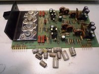
The Thoebe and Thaedra I (one) had the same line stage. The picture you posted is the line stage from Thaedra II (two). The alignments on that board are a pain in the ***. Try emailing Mike at GASAUDIO, he is the only one left willing to talk about these classic pieces. Or possibly he will chime in here.
I have two Ampzilla IIa, a Son of Ampzilla, a Grandson of Ampzilla, a Thaedra II, and a Thalia, all I need is a Thoebe.
Craig
I have two Ampzilla IIa, a Son of Ampzilla, a Grandson of Ampzilla, a Thaedra II, and a Thalia, all I need is a Thoebe.
Craig
Hi. Perhaps someone can help me. I am not an electronics guy but can do basic repairs. I work as a sound engineer and understand how to work safely on things. I am trying to repair one of these units but live on a small Caribbean island and no one local is up to the task.
I have signal on both channels to the headphone outputs but nothing on the main outputs except for a fairly loud buzzing on one channel.
Any help would be greatly appreciated.
Regards
Pat
I have signal on both channels to the headphone outputs but nothing on the main outputs except for a fairly loud buzzing on one channel.
Any help would be greatly appreciated.
Regards
Pat
The output from the line stage is the same as the pre amp output and the headphone signal. So if your headphones sound OK then it has to be the output relay or it's circuitry. The relay circuitry provides a time delay when the pre amp is first turned on BUT it also disconnects the output jacks when the headphones are plugged in. What color is the LED? Green is a Thaedra I, red is a II. I can get more info when I get home this afternoon.
Craig
Craig
There were two different relays used in the Thaedra, what I don't know is if one type was in the I and the second type in the II. My II has a relay that I don't think is the mercury wetted type. I will have a Thaedra I on Wednesday so I'll check it then.
Anyway like said DJK you want to keep the relay if at all possible. Again depending on the version you have the relay may be mounted on the mother board OR on a separate plug in card between the regulator and line stage PCBs. The plug in card's connector is labeled so it would be easy to remove the card, solder in some TEMPORARY jumpers until the real problem is found. It may not be the relay but the relay circuit, it has been problematic in some versions. The bottom headphone jack is the switching jack, it de-energizes the relay killing the line outs leaving the headphones working. The upper jack appears to leave the line outs active.
Craig
Well I got my Thaedra I yesterday and of course it was bad, don't remember if it was supposed to be dead or alive.
The left channel of the line stage was bad, the resistor supplying the servo IC was fried, replaced the resistor and 1458 opamp, line stage good to go for now.
The regulator card had some issues also, leaking capacitors, and one of the positive regulators was passing the input voltage. Replaced the eight large electrolytics. Replaced the all of the pass transistors, one was shorted and that took out the 1458 opamp also.
Anyway I'm ready for questions on the Thaedra in question. The relay is on the motherboard in this particular version.
Craig
- Status
- This old topic is closed. If you want to reopen this topic, contact a moderator using the "Report Post" button.
- Home
- Amplifiers
- Solid State
- GAS Thaedra