I would doubt that they would be able to divulge any information that could not be gleamed from reading the data sheets for any chips used and examining the reference designs. They would not want to give any hints to competitors who are probably trying to gleam any revelations from the design.
Looking at the photos, the PCB is a high density interconnect (HDI) PCB, with micro-via's in pad and filled. Conventional PTH vias (the line at the back) probably connected to the 0V (GND) to form at least a partial shield. This type of PCB construction is beyond the ability of DIYers or Commercial companies to modify apart from some restricted changes such as changine device values. That is why it is common on these sort of designs to see 0 ohm resistors and places for extra components, unpopulated. These are variant designs, there is an choice of circuitry built in to the PCB to allow modification at a leter date, or just to vary features between models of the device.
Have a look around this site if you want to get some idea of PCB's these days, their HDI part is one of the best for information.
Wrth Elektronik - Printed Circuit Boards | Wrth Elektronik: Printed Circuit Boards > Welcome
")
Looking at the photos, the PCB is a high density interconnect (HDI) PCB, with micro-via's in pad and filled. Conventional PTH vias (the line at the back) probably connected to the 0V (GND) to form at least a partial shield. This type of PCB construction is beyond the ability of DIYers or Commercial companies to modify apart from some restricted changes such as changine device values. That is why it is common on these sort of designs to see 0 ohm resistors and places for extra components, unpopulated. These are variant designs, there is an choice of circuitry built in to the PCB to allow modification at a leter date, or just to vary features between models of the device.
Have a look around this site if you want to get some idea of PCB's these days, their HDI part is one of the best for information.
Wrth Elektronik - Printed Circuit Boards | Wrth Elektronik: Printed Circuit Boards > Welcome
It could be very nice and interesting to read a comment from an Samsung designer just about this subject. This it may be a real event for all of us!
Maybe will come one day...
why? do you think they would disagree with their own decision? presumably, given this is not the first mobile communications/media device they have made... they had some sort of reason for it being there... the type of circuit you describe is not rocket science, you will find something like it on every single mobile phone
Thanks marce for your explanations, intervention, contribution.
I think this it should be the right way this thread/forum should function: changing of informations and helping each other with each findings/knowledge. Not only disgusting superiorities empty of content displayed of some...
I think this it should be the right way this thread/forum should function: changing of informations and helping each other with each findings/knowledge. Not only disgusting superiorities empty of content displayed of some...
Coris, its you with the superiority complex, you dont see that? i'm not the one claiming to know better than the samsung designers and make audible improvements by removing vital parts of the circuit they installed in a what 3rd or 4th gen galaxy? these claims are made despite not knowing what the response of the filter is before, or after the change. It doesnt make me feel smart to point out basic errors, it makes me frustrated that I have to correct such mystical claims on a technical forum.
Coris, its you with the superiority complex, you dont see that? i'm not the one claiming to know better than the samsung designers and make audible improvements by removing vital parts of the circuit they installed in a what 3rd or 4th gen galaxy? these claims are made despite not knowing what the response of the filter is before, or after the change. It doesnt make me feel smart to point out basic errors, it makes me frustrated that I have to correct such mystical claims on a technical forum.
I`m just tired now of your interventions and way to be a DIY member. I think we got more than enough with you here. There is not the meaning of this thread/forum to never ending struggle with such kind of peoples like you.
Do you have some competent technical facts to contribute with to the subject of this thread, you welcome. Else just go away with your frustrations and general comments about how the thing it should work in your world.
I`ve made some quick measurements on the modded device. I should took the same before, but unfortunately I have not done it... I`m waiting now for some tools to make easy to me to get inside the phone, and I will take a closer look afterwards...
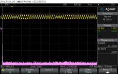
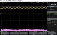
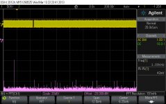
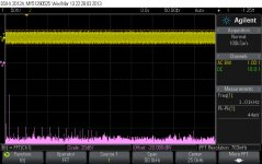
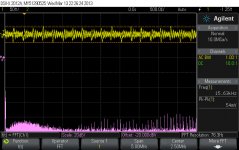
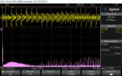
The result of the measurements are quite contradictory. I`m quite convinced that removing of that filtering caps have not big impact for the results pictured here, even though an perceptual improvement for the sound. There may be the DAC which is working so. Even though the all bad to be seen in those pictures, the sound is further very good.
It still an enough big paradox in all this: I can notice some sort of intermodulation distortions in very low end of the spectre, in some special audio circumstances, but the pictures shows the best right in this area. I can not hear something bad in the high end of the spectre, the sound is very detailed and fine, but what is to be seen in those pictures for the high end of audio spectre is quite a disaster... BTW, "hearing" an 18-20Khz sine wave played out on the headphones is a real catastrophe... Only distorted sound! But music come out just fine...
The environment of those quick measurements: I have generated sine wav files (24bit) with the respective frequencies. The files are played out just neutral (no filtering/equaliser or so). No any difference between sample rates. I used both 48Khz (DAC native) and 192Khz. The same bad or good signals out, no matter the sample frequency. No load on the outputted signal. Headphones connected introduce some HF noises (antenna) which it mess the oscilloscope. Is a quite low output level from the DAC...
I think to come back on those measurements (more accurate) another/next time...
Attachments
Last edited:
The capacitors are likely there to prevent RF ingress and rectification. Having firsthand experience with the EMC testing of such a device, any amplifier pins without RF filtering may cause the device to fail radiated harmonic emissions testing.
The TX power levels in a cellular phone can be very high. Up to +33 dBm for a 850/900 band GSM phone call. Even though it is the output of an amplifier, there still may be a problem. You may even cause the device to generate distortion in the audible range when the radios are transmitting by removing those caps.
The TX power levels in a cellular phone can be very high. Up to +33 dBm for a 850/900 band GSM phone call. Even though it is the output of an amplifier, there still may be a problem. You may even cause the device to generate distortion in the audible range when the radios are transmitting by removing those caps.
Last edited:
as i've said over and over again; in what world does testing for basic (ie pure tonal) interference at audio frequencies only do anything? when did I ever suggest some sort of audio tone would be evident?
Your test does not illustrate any improvement vs what it was before either, you dont say anything about making a or receiving a phonecall, receiving a GSM location ping, so remind me, what were your tests designed to show? that you deem them somehow conclusive is confusing...
Your test does not illustrate any improvement vs what it was before either, you dont say anything about making a or receiving a phonecall, receiving a GSM location ping, so remind me, what were your tests designed to show? that you deem them somehow conclusive is confusing...
Last edited:
See http://www.analog.com/static/imported-files/tutorials/MT-096.pdf
Particularly, Figure 7 on page 9.
Particularly, Figure 7 on page 9.
yep, thats why I suggested having the radio active, I think everyone has heard the high energy rectified ping directly before a phonecall, thats the most obvious one. that will be just part of the reason that Common mode+Differential filter is there (the series of parts the caps are part of at the output). you are right of course about the possibility of IMD as well.
Coris will just say he doesnt hear a problem, only wonderful open music... its pattern behavior when doing stuff like this.
Coris will just say he doesnt hear a problem, only wonderful open music... its pattern behavior when doing stuff like this.
Thanks chris719 for your in fact intervention/contribution. Is just fortunate that those things come out and the all of us interest in this can learn/experience more. I think this is the right way to go further, and the meaning of a forum. A such debate can leads to something positive, not only expressing "frustrations" out in one or more threads here...
I will take a more closer look at those aspects and details...
I will take a more closer look at those aspects and details...
I`ve gone through the publication in chris719 link. Interesting stuff indeed and god to know.
For this case there is this part which apply:
"amplifier outputs also need to be protected from EMI/RFI, especially if they must drive long lengths of cable, which act as antennas. RF signals received on an output line can couple back into the amplifier input where it is rectified, and appears again on the output as an offset shift.
A resistor and/or ferrite bead, or both, in series with the output is the simplest and least expensive output filter..."
Some comments... The Wolfson WM1811 is a DAC chip made special for mobile phones use. It has included a control circuit for the outputs offset correction. So in this case the effects of RFI rectifications are most minimized, of even removed. Even though the designers of Note 2 have chosen to place an pi filter on the DAC output, for headphones.
At this moment I`m quite unsure if the ferrite bead supposed to be part of that pi filter is in fact a ferrite bead. It may be an capacitor (the functional description of WM1811 refer to a smaller capacity necessary on the DAC outputs for headphone use...). I shall verify this soon...
In the quoted text above is about a simple/cheap method to prevent RFI induced in the chip outputs. This method (resistor/bead) suggested is more "friendly" in case of an audio signal, than use of filtering caps (relatively big capacity) to the GND on that output.
My temporary conclusion is (still be) that removing of that caps it may not have main negative impact in the behaviour of the DAC chip and its functionality.
Still yet to be analyzed why so bad signals on those picture here, and why the perceptual improvement in SQ without those filtering caps in place...
The case is under further treatment...
Last edited:
Whatever Coris, as usual you will read into the information provided what you want to hear and ignore the rest. thats why i've lost patience with you and now simply correct your errors for others. You dont even know what they did, what frequencies they were targeted at, what is happening now they are missing etc.
such small shunt caps CANNOT pass audio. they are part of a compound filter with both common mode and differential elements and you have thrown out/altered the response of this filter as well as leaving the noise they are there to filter, to bounce around in the circuit. they are not there to filter DC offset (they are parallel/shunt caps...), but omitting them may mean that the noise (an RF/AC signal) they were supposed to filter out, is rectified to DC error by the opamp internal structure, 2 different things. the dac having DC offset circuitry has nothing to do with it and provides no protection against it...
similar to what you are doing with your other tweaks like too much gain than you can use, too high clockspeed than the dac can use etc. you are hearing what you want to hear.
You present your mods for others on this and other less technical forums where they may go unchallenged, take pictures, talk up the benefits etc. before doing such things, its my view that it is your responsibility to know or at least have some idea what they do before promoting them for others and declaring improvements based on a single subjective assessment; especially ones like this where it would be easy to zap the board with ESD and warranties are voided.
only now that myself, marce and Chris have challenged you have you done any investigation at all...
Last edited:
It seems that "correct errors for others" is the only your contribution to this forum, in the threads and for your "clients" you scan for "errors". I see that is not only me you "correct the errors" for, but everybody everywhere... in this forum. Is a quite bizarre contribution from your part... This maybe give you the feeling that you are free for errors, and over everybody else. In fact your "correction" it were only to agree to the pertinent intervention of chris719
But anyway, the world is not perfect... Happy correction further!
But anyway, the world is not perfect... Happy correction further!
Last edited:
not at all, I make errors regularly, its part of learning and I learn something most days, but I dont tend to promote my errors as advancing the performance of well engineered devices, or rewriting the laws of physics.
I try to read up and understand, before proclaiming anything and if i'm wrong, I expect to be and welcome being corrected, because it means i've learnt something.
I dont get a kick out of correcting misunderstandings of electronics, it annoys me when people like yourself make such hard work of it, because you are so stubbornly wanting to believe you are doing good; but I do feel that being a technical forum where people go for advice, that blatant falsehoods should not be left unanswered.
Last edited:
A forum is that place where people discuss most on subjects, and come with their findings (theoretical and factual) for that purposes to be discussed. Asking for advice is an only small part of an forum... Is not supposing that one or few members entitle himself to watch for errors to be corrected for all others...
But I really think that such philosophical discussion is out of topic here... That because I will stop to answer you from now on.
But I really think that such philosophical discussion is out of topic here... That because I will stop to answer you from now on.
The ferrite bead is there to make a pi filter that operates in the high MHzs while being effectivly transparent at lower frequencies. The bead will have quoted resistances at certain frequecies 60M 100M 1G, use this figure in a pi filter calculatore with the value of the caps and it will give you the attenuation figure for the frequecies of interest. Using a resistor would have an effect at all frequecies especially the audio levels witch is not what we want. This is common practice on digital boards, not only for connections to leads, but to create power islands from a main supply plane to isolate more sensitive circuitry from high frequency noise where adding a seperate LDO is not doable for a variet of reasons or is overkill.
- Status
- This old topic is closed. If you want to reopen this topic, contact a moderator using the "Report Post" button.
- Home
- Source & Line
- Digital Line Level
- Galaxy Note 2 - audio stage mods, discussions, improvements ideas