Originally posted by XELB
Bigger the Thick of the cable lower the resistor.
This is one of the reasons why thick and good conductivity gives you punchy bass.
Don't really want to start a cable discussion...
Even skinny wire's R is probably insignificant compared to the wire in the voice coil....
In most instances i'm using skinny solid core wire for improved sonics....
dave
carlosfm said:
Punchy bass alone doesn't make a good sound.
Too much is too much, too little is too little.
There's a spot for everything.")
Yes, that's right. But it also deppends on the taste of each one...
(I don't like too much)
And btw, the shorter the speaker cables, the better.
That's why I told that bigger the cable more power you lose!
( microscopical Ohm law )
XELB said:That's why I told that bigger the cable more power you lose!
( microscopical Ohm law )
But you give too much importance on the least important parameter for a speaker cable: resistance.
XELB said:I test them and if I like their sound, I take them home
You should test at home.

XELB said:Resistance is for picky persons
But if you want to know scientifically how a cable affects the sound, that's a starting point!
Compared to inductance, and (specially) capacitance, resistance is what has less impact on the sound.
As long as you don't use carbon cables.
If you could have all these three parameters at very low values, you would have a unique cable.
Not possible, though...

I allways test at home
I take my amp to a friend shop, test it with the same speakers I have at home and if I like them(cables), I bring them home for the final test.
(I like to test them with the accustic of my listen room)
Inductance and capacitance in cables are very difficult to talk about... this not only deppends in the material you use but also in the construction of the cable.
The construction can also affect resistance but, resistance is allways more "connected" to the quality of the material then to construction.
XELB said:
Bigger the Thick of the cable lower the resistor.
(and bigger the distance between the amp and the speakers, bigger the power you lose)
If you want to have the same output power with a thin cable, the thin cable must have better conductivity.
And altough thicknes of single UTP Wire is sooo thin - it's still very hard to measure resistance with DMM - or better said - comparing thick snake-look-a-like beast with that single UTP wire shows same result - around 0,1R ...
But you should not forget that the "snake type beast" has a potetnial big skin effect ...
carlosfm said:
Punchy bass alone doesn't make a good sound.
Too much is too much, too little is too little.
There's a spot for everything.
And btw, the shorter the speaker cables, the better.
Both statements are something I very agree with!!!
CRC and regs
Btw - one Q - last weekend I tried another PSU layout for my GC preamp section - carlos advised me some time ago to use CRC + regs - so with using what having on hand I've done newt combination:
1000uF/25V PanFC ---- 110R ---- 1000uF/25V PanFC --- L7815
1000uF/25V PanFC ---- 110R ---- 1000uF/25V PanFC --- L7915
BUT - on one resistor the voltage drop is higher for 0,5V?!?! Is that because positive and negative regs draw different currents (OK, that would be logical then) - or is something else wrong here ...
Btw - I've made a mistake at first test - forgot to connect "gnd" from two gretz bridges to gnd pf caps and regs - so for a short time on one pair of PanFCs there were 33V - but that's like few seconds - and they seem to work OK ...
Upupa Epops said:Typical capacitance of speaker cable is for PA's output insignificat.
Typical yes, but there are some weird cables out there.
Not for me, thanks.
High capacitive cables always affect the treble (they make a low-pass filter, in fact) and the bass gets untight too.
I'm talking weird things like the top of the range Wireworld cables (coaxial), which sound horrible with most amps, cheap cable is much better.
Kimber 8TC doesn't go with some amps too, while the 4TC is ok.
The 8TC and the Wireworlds are high capacitance cables.
For the diyers: crossing too much Cat5 cable is throwing away the baby with the water.
Resistance doesn't tell me much, a cable that has 2.9 ohms resistance for 1 Km (!) doesn't have to sound good. I mean: Supra Classic 6.0.
Re: CRC and regs
The 79xx regs usually draw a little more current.
Are you worried about a 0.5v difference before the regs?
Stabist said:1000uF/25V PanFC ---- 110R ---- 1000uF/25V PanFC --- L7815
1000uF/25V PanFC ---- 110R ---- 1000uF/25V PanFC --- L7915
BUT - on one resistor the voltage drop is higher for 0,5V?!?! Is that because positive and negative regs draw different currents (OK, that would be logical then) - or is something else wrong here ...
The 79xx regs usually draw a little more current.
Are you worried about a 0.5v difference before the regs?
Re: Re: CRC and regs
Not woried - but I'm learning - and this was some new fact for me ... All cleared and solved out now
carlosfm said:
The 79xx regs usually draw a little more current.
Are you worried about a 0.5v difference before the regs?
Not woried - but I'm learning - and this was some new fact for me ... All cleared and solved out now
Upupa Epops said:Low pass filter ? By Zout = 0.1 Ohm or less ? It must be realy " high capacitance cabel ".
You have to count with the speaker.
GainConcept No.3
Quite some time ago I've started this topic - and the first post contained also the quoted part ...
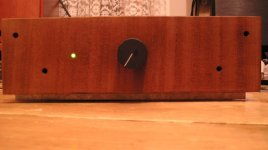
Well - now I can finnaly present to you GC No.3
At that time it looked like this:
Stabist said:In last months I've been quite GainBuildingMan ...
........... then experimenting by OPA541/OPA2604 combination (which shows a lot of potential but it still needs a proper chassis) ........
Quite some time ago I've started this topic - and the first post contained also the quoted part ...
Well - now I can finnaly present to you GC No.3
At that time it looked like this:
Attachments
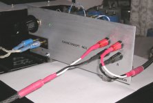
As said - that didn't seem a proper chassis to me - because it was to open and also quite ugly ...
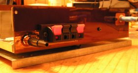
But since I didn't find time or motivation to realize some "heavy" Al chassis - but still wanted to finish somehow this project - I've decided to give another shot with "recycling" method
So some old Nokia switcher donated the base for the chassis ...
And then it was combined with some acryl at the back .....
Attachments
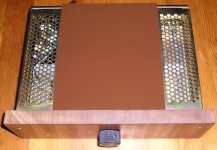
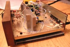
And this are the guts ...
Trannie is/will be in separate chassis (at the moment I use the trannie of my "PatekLine GC"
Then there is snubberized PSU.
And as said - a combination of OPA541 and (at the moment) OPA2604.
And attenuator is DiY made - simple 2x12 steps switch converted to attenuator ...
Nothing special ..
Trannie is/will be in separate chassis (at the moment I use the trannie of my "PatekLine GC"
Then there is snubberized PSU.
And as said - a combination of OPA541 and (at the moment) OPA2604.
And attenuator is DiY made - simple 2x12 steps switch converted to attenuator ...
Nothing special ..
Attachments
- Status
- This old topic is closed. If you want to reopen this topic, contact a moderator using the "Report Post" button.
- Home
- Amplifiers
- Chip Amps
- GainConcept No.5