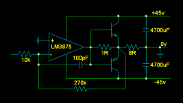
Today I was reading a blurb on the Quad 405 current dumping amplifier and how it works and I decided you could do it with basically a power opamp and a pair of big bipolars. Now the LM3875 is basically a power opamp and the good thing is that it will tolerate at least + / - 45 volt rails. The catch is that you can't pull a lot of current out of it with really high rails, but in this situation we don't really need to.
How it works is the 8 ohm output is driven through the 1 ohm current sensing resistor. Seeing this resistor is inside the feedback loop it sort of disappears so the speaker can't see it. Now when the voltage drop across this resistor is more than 0.6 volts either polarity, (voltage across 8 ohm load would be 4.8 volts either polarity) the base of one of the output transistors start to get pushed too. These transistors decide that the LM3875 needs a bit of help so they take over the majority of the work driving the speaker. Use big transistors here, BTW.
The big deal about this cct is that it has no biasing for the transistors, no thermal drift problems, no emitter resistors, no adjustments, no nuthin'. Nonlinearity of the output transistor doesn't matter a toot. You should be able to drive as low an impedance load as you want, given suitable output transistors.
I haven't built it yet; just thought I'd throw the idea into the wind.
Attachments
Hi,
This has been done before, notably with the TDA2030:
http://www.dice.ucl.ac.be/~morelle/data sheet/CIRCUIT INTEGRE/TDA/TDA2030.pdf
I don't know whether it has been used using the higher voltage LM's, but you make it sound very good")
Dirk
This has been done before, notably with the TDA2030:
http://www.dice.ucl.ac.be/~morelle/data sheet/CIRCUIT INTEGRE/TDA/TDA2030.pdf
I don't know whether it has been used using the higher voltage LM's, but you make it sound very good
Dirk
Bricolo said:why using a power opamp?
I think this shematic would work with a classical opamp, so...
For a 600mV drop across a 1 ohm resistor you'd need 600mA output. That's beyond most opamps I'm aware of.
If you're going to use a regular opamp then you'll need to bias the transistors into class B inside the feedback loop. That nullifies the benefits here.
Most affordable nice sounding opamps like OPA604,627,134... won´t take more than +-18V or +-24V at maximum.why using a power opamp?
I think this shematic would work with a classical opamp, so...
But +-45V seems even too high with the LM3875.
I think there was some thread about a gainclone sounding real bad due to too high voltage even at low volumes and so low current demands.
That´s the one : http://www.diyaudio.com/forums/showthread.php?threadid=13593&highlight=gainclone+sony
http://www.diyaudio.com/forums/showthread.php?threadid=13684&highlight=gainclone+sony
Jens
Here's a thought...
What about using a plain, boring old opamp that can handle those rails, then put a push-pull emitter-follower type class A stage hanging off of it in the feedback loop to get the power you need. It shouldn't be too hard to find parts that can handle those rails...
What about using a plain, boring old opamp that can handle those rails, then put a push-pull emitter-follower type class A stage hanging off of it in the feedback loop to get the power you need. It shouldn't be too hard to find parts that can handle those rails...
Hi, I know this is a little off topic, but would this metthod work in producing a precision power regulator, asing a high speed (lower voltage and current) op-am? As, I was thinking of the best way to produce a good discreet (if you can call it that using an op-amp) power regulator for a new DAC design I was hoping to strat work on.
Circlotron said:The big deal about this cct is that it has no biasing for the transistors, no thermal drift problems, no emitter resistors, no adjustments, no nuthin'. Nonlinearity of the output transistor doesn't matter a toot. You should be able to drive as low an impedance load as you want, given suitable output transistors.
I haven't built it yet; just thought I'd throw the idea into the wind.
It'll probably work, but the cross over distortion will start to kill you at 10kHz. It may not be very stable. The output of the power opamp will have to jump from +Vbe to -Vbe below your output signal to drive a linear output. Basically, It will be driving a nonlinear signal to create a linear signal at the output. This will probably work at well at lower frequencies (Maybe a great amp for Bass), but will start to give cross over distortion at higher frequencies with higher power levels. the 100pf cap will probably not help the disto any.
But, I'd say build the thing and try it. If the output of the power opamp is fast enough, the disto will be low.
Just my 2 cents!
-Dan
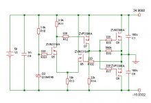
bigparsnip said:Hi, I know this is a little off topic, but would this metthod work in producing a precision power regulator, asing a high speed (lower voltage and current) op-am? As, I was thinking of the best way to produce a good discreet (if you can call it that using an op-amp) power regulator for a new DAC design I was hoping to strat work on.
You can use this principle for virtual ground, I have used it lot´s of time both in poweramps and preamps, and last in my audio part of my CDplayer.
Attachments
Not trying to be contradictory or anything...
Not so! The part where you expect to see crossover distortion, the load is actually being driven by the opamp via the 1R resistor. When the voltage drop in that resistor is high enough (which means there is actually current from the opamp flowing into the load) the bipolar starts to help. Sooo..... no xover distortion.dkemppai said:The output of the power opamp will have to jump from +Vbe to -Vbe below your output signal to drive a linear output.
Re: Not trying to be contradictory or anything...
At just below Vbe, the opamp will be driving all of the current into the load. At just above vbe, the transistor will be driving all of the load. In my opinion, that will be a non linear current for the opamp. The opamp sees a gain of something less than one, and then suddenly a gain of 50. Again, this may work well at low frequencies, but at some high frequency you will start to see some cross over distortion. (Again, the disto may not be the "standard" step distortion, but some sort of distortion will exist at the cross over area.
I'm not saying it won't work. I'm just saying that I would expect to see disto at higher frequencies.
Build it, and test it. I'd be curious to know how it works out!
-Dan
Circlotron said:
Not so! The part where you expect to see crossover distortion, the load is actually being driven by the opamp via the 1R resistor. When the voltage drop in that resistor is high enough (which means there is actually current from the opamp flowing into the load) the bipolar starts to help. Sooo..... no xover distortion.
At just below Vbe, the opamp will be driving all of the current into the load. At just above vbe, the transistor will be driving all of the load. In my opinion, that will be a non linear current for the opamp. The opamp sees a gain of something less than one, and then suddenly a gain of 50. Again, this may work well at low frequencies, but at some high frequency you will start to see some cross over distortion. (Again, the disto may not be the "standard" step distortion, but some sort of distortion will exist at the cross over area.
I'm not saying it won't work. I'm just saying that I would expect to see disto at higher frequencies.
Build it, and test it. I'd be curious to know how it works out!
-Dan
anyone else built one
hi Circlotron,
saw this and liked the idea and its simplicity so I thought Id try it.
I used a lm3875 (tried opa549 and 3886 and prefer this by a long shot) Toshiba 1302 and 3281, a 160 va 25 0 25 and a 500va 30 0 30. think the output transitor dc rails were + - 45 volts.
Im going to get some sine waves from some where and look on a scope cos it seems to clip if I crank it up loud, but its a funny distortion, not like normal clipping?
Whether or not I prefer this to my lm3875 IGC has not been so clear this time. The lm3875 IGC has blown away 4 amps Ive compared it to so far but this is a nice sound. Its not as smooth as the IGC , but the bass is better more controlled, sound is more detailed and clearer,
I really like it but I also rate my straight IGC, will wait a bit longer before I put it in a box
Also want to try the Joe Ramussmen tube front end on it and see how it sounds. Another Idea I had was to put a couple of mosfets on the output instead of transistors, think a couple of 2sk1530 and j201 would work? From memory fets need more voltage to turn on, would this cause a problem?
seeya arthur
From memory fets need more voltage to turn on, would this cause a problem?
i assume it would increase THD.
Regards
Charles
- Status
- This old topic is closed. If you want to reopen this topic, contact a moderator using the "Report Post" button.
- Home
- Amplifiers
- Chip Amps
- Gainclone with current-dumping afterburner!!