No question speakers and headphones are radically different, but if it won't pass the headphone test, forget the speaker test. IMO, if there's a buzz, there's almost certainly a wiring error with the power and ground. And if that's the case, it will affect the sound as well. Can you draw a diagram showing the physical power supply connections?
I may post the drawing tomorrow, but assuming that the buzz is only audible when using high sensitivity headphones I guess it's a problem of not using a toroidal transformer and bad interconnects. Drawing is all-star (V+, V-, 0V both signal and power go to the same three points) and not earthed. It may exist a ground loop between input jack and volume trimpot.
A proper "star" ground isn't as simple as often thought. You have to put a stub off the filter caps, and avoid any rectified charging currents in the star ground at the end of the stub. Sometimes, for amp stability, the star point has to be far removed from the filter caps, but there's still a preferred order to connect the various items to be grounded. The only hum you could possibly hear should be from the transformers magnetic field, and toroids won't always fix that. Though advertised as having the lowest external field, they're not as perfect as you might think. IMO, you might see it on a scope, but it still shouldn't be audible.
buzz gone
Finally the buzz is gone. I've replaced the wires between input, trimpot and board with screened ones and changed the external interconnect.
Thanks Conrad for the advise with decouplig caps
Is it possible to connect the signal ground to the power ground through a small choke?
Finally the buzz is gone. I've replaced the wires between input, trimpot and board with screened ones and changed the external interconnect.
Thanks Conrad for the advise with decouplig caps
Is it possible to connect the signal ground to the power ground through a small choke?
Now I'm doing a BPA-200 without the feedback cap and with similar features than my buffered single-ended design.
Has anyone listened to a BPA200 with 20k/1K feedback and without feedback cap?
I know that this is a rather dangerous design, but i've matched each resistor with very high accuracy and decoupling network is prior to the buffer ic so there won't fighting because of poorly matched input cap, which usually has 10% tolerance.
Another question, the LM3886 ground should be connected to signal or power ground?
Looks like an old thread but is what I'm doing at the moment. I've been running a dual-mono LM3875 DIY amp for a while now, have built a few speakers and experimented with crossovers on all of them but this was my first amp. I've built and tested one 3 way line level X-O and am happy with the results so starting on its friend soon. The end result will be using the same power supplies for 6 channels and speakers built to match.
I do want to get a better understanding of what is meant by Conrad (above) by putting a stub off the filter caps and what is the preferred order for connecting to the ground. I have the signal grounds on a bolt first, then the earth line to the earth mains, power ground next then it's bolted to the chassis. Any info or hints would be great as I don't know anyone else that builds amps (well one guy who has made a valve guitar amp, not really helpful to me) so fresh thoughts can be great.
Thanks.
Hi Pancakes, I'm not sure what "putting a stub off the filter caps" means, but here is my grounding arrangement for my GainClone. I have no hum in the speakers and I am astonished at the sound quality of the amp.
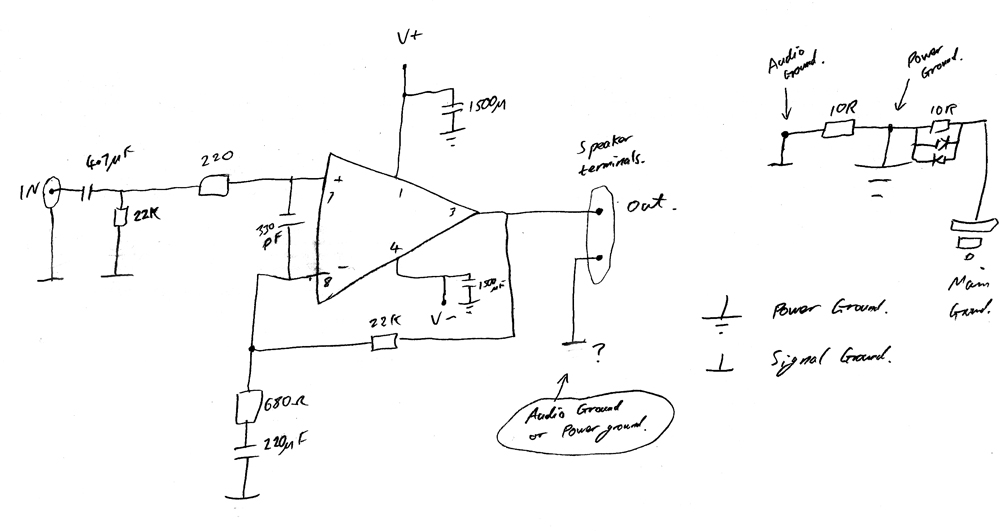
(Please note, the circled part that says "Audio Ground or Power Ground" is connected to Power Ground)
(Also, I have back to back diodes across the 10 Ohm resistor connecting power ground to audio ground)
I was discussing this in this thread:
http://www.diyaudio.com/forums/chip-amps/161432-ebay-gainclone-pcbs-2.html
My first GainClone amp:
http://www.diyaudio.com/forums/chip-amps/79303-chip-amp-photo-gallery-137.html (Post 1363)
Last edited:
Hi,
your diagram looks good and you have confirmed that speaker return is taken to power ground. That's OK.
The wires connecting the transformer secondaries to the rectifiers and then on to the smoothing capacitors pass very spikey current waveforms repeating at 100Hz. These wires should be twisted together to minimise the loop area and thus minimise the radiated energy from the loops.
The high peak currents generate high peak voltages around that closed circuit. Keep these twisted pairs as short as possible, AFTER you have oriented the transformer for minimum measured hum.
This means for us builders that the Audio Ground MUST NEVER be located on the rectifier loop.
Instead take a wire from the zero volts of the smoothing capacitors along with the +ve feed wire and the -ve feed wire and twist these as a triplet. Take the triplet to the amplifier and there separate out the zero volts wire and connect it to the Audio ground. Keep the twisted triplet as short as possible.
I've actually taken V+GND and V-GND separately from the rectifiers and platted them (bottom left of the picture):
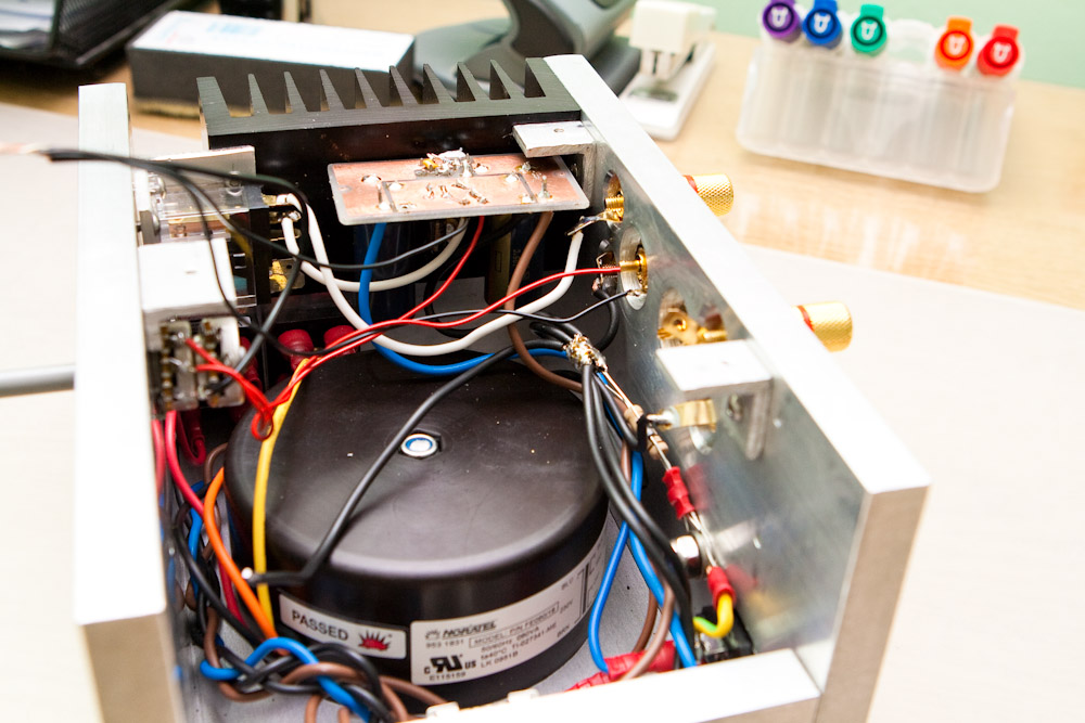
This seems to work very well, and I have no hum in my speakers. by using a 10Ohm resistor and back to back diodes as AndrewT mentioned in another thread really does a good job of breaking ground loops. On an experimental setup I was playing around with, I had a slight hum in the speaker, then I attached the Resistor/diode arrangement, and bang....it was gone.
This seems to work very well, and I have no hum in my speakers. by using a 10Ohm resistor and back to back diodes as AndrewT mentioned in another thread really does a good job of breaking ground loops. On an experimental setup I was playing around with, I had a slight hum in the speaker, then I attached the Resistor/diode arrangement, and bang....it was gone.
- Status
- This old topic is closed. If you want to reopen this topic, contact a moderator using the "Report Post" button.
- Home
- Amplifiers
- Chip Amps
- gainclone sound differences