soundNERD said:That looks really good! It looks like you designed it in Eagle using a copper pour. If you don't mind telling me, how do you do that? I've been trying to do copper pour for a long time and could never figure out how to.
Thanks!
To do a copper pour in eagle you use the polygon tool (not the rectangel tool).
1. Place your components and connect them with the signal tool.
2. Use the Name tool to name the signals.
3. Draw your "copper pour" area with the polygon tool.
4. Use the Name tool to name the polygon the same as the signal you want to attach it to.
5. Use the change tool to adjust things like isolation, and thermals etc.
Good luck
Re: OPA541 Design
Nice PCB layout") . if you have some OPA 549 spares, i would go for this coz it has more power than the OPA541. Yup, i also use the DRV134 for the bridging. the low pass filter i use is fixed though quite simple and easy to build.
. if you have some OPA 549 spares, i would go for this coz it has more power than the OPA541. Yup, i also use the DRV134 for the bridging. the low pass filter i use is fixed though quite simple and easy to build.
The sub i built is unregulated with a pair of 30,000uF caps. I can post the internals if its okay
Gcollier said:Hello all, I have also been thinking about putting together a sub amp to replace y current underpowered unit. My plan is to use a pair of bridged non-inverted OPA541's. The bridging will be accomplished with a DRV134 similar to Digi's design. I have attached my first draft of a PCB. The plan is to use two of these and mount the bridging board in between. Obviously the caps on board are a bit small for a sub, there will be a pair of 6800uF caps on the PSU board. I'm going to try unregulated first as I would like to keep it as simple as possible. I really don't need a filter of any sort as I am using this with an HT preamp that has a sub out, If I do add one I'll likely just use an adjustable active lowpass filter with an OPA134...cheap and simple.
G.
Nice PCB layout
. if you have some OPA 549 spares, i would go for this coz it has more power than the OPA541. Yup, i also use the DRV134 for the bridging. the low pass filter i use is fixed though quite simple and easy to build.The sub i built is unregulated with a pair of 30,000uF caps. I can post the internals if its okay
Re: Re: OPA541 Design
I'd luv to see the internals
rmpmla said:
Nice PCB layout
The sub i built is unregulated with a pair of 30,000uF caps. I can post the internals if its okay
I'd luv to see the internals
Re: Re: Re: OPA541 Design
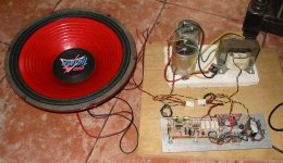
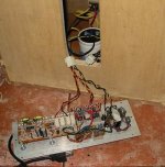
here it is before installation unto the enclosure.
Gcollier said:
I'd luv to see the internals
here it is before installation unto the enclosure.
Attachments
Once you are done with the amp part of your project, you may want to have a little look at this.
I ran into problems putting together a crossover that was simple and adjustable and had some documentation. So I stripped parts and ideas from a few different websites and put this together.
http://www.diyaudio.com/forums/showthread.php?s=&threadid=33067
Use it or don’t, but if you read it you may learn a little something about putting together a crossover for a sub (or you may not…) I tried to document my learning about things as I went along.
And you may be surprised at the output of your sub. My 2 lm3886's can shake the whole damn house.
officeboy said:Once you are done with the amp part of your project, you may want to have a little look at this.
I ran into problems putting together a crossover that was simple and adjustable and had some documentation. So I stripped parts and ideas from a few different websites and put this together.
http://www.diyaudio.com/forums/showthread.php?s=&threadid=33067
Use it or don’t, but if you read it you may learn a little something about putting together a crossover for a sub (or you may not…) I tried to document my learning about things as I went along.
And you may be surprised at the output of your sub. My 2 lm3886's can shake the whole damn house.
TI has a very good and simple filter design white paper and software on their website. I haven't actually built anything with it yet, but the actual circuts look easy enough.
I never have made a variable crossover. Instead I use WinISD Pro Alpha and use the 2nd order active lowpass filter calculator.
I've had no problems yet, and every crossover I've made seems to work perfectly fine.
You should be able to make a variable crossover with it, though. Just choose a capacitor value, then figure the resistor values needed for the lowest cutoff freq. and the highest cutoff freq. Then find a potentiometer to match those requirements.
Gcollier said:
To do a copper pour in eagle you use the polygon tool (not the rectangel tool).
1. Place your components and connect them with the signal tool.
2. Use the Name tool to name the signals.
3. Draw your "copper pour" area with the polygon tool.
4. Use the Name tool to name the polygon the same as the signal you want to attach it to.
5. Use the change tool to adjust things like isolation, and thermals etc.
Good luck
Thanks. I tried that But I cannot get it to work. It works perfectly when I draw the polygon and then name them both the same thing, but once I save and close Eagle, if I open it back up, the copper pour is gone and it's just back to the original bright blue lines I drew to make the polygon, but it's not filled in.
Also, it often doesn't turn bright blue when I do the copper pour. Instead I use the polygon tool, make the drawing, and when I close the design, it should turn bright blue and stay there once I click out of it, but sometimes it doesn't. And the only way to fix that is to exit and re-start Eagle.
Any ideas on why this is happening? I have Version 4.13r1 if that matters. What version are you using? I think this may be a glitch or something in this version.
soundNERD said:
Thanks. I tried that But I cannot get it to work. It works perfectly when I draw the polygon and then name them both the same thing, but once I save and close Eagle, if I open it back up, the copper pour is gone and it's just back to the original bright blue lines I drew to make the polygon, but it's not filled in.
Also, it often doesn't turn bright blue when I do the copper pour. Instead I use the polygon tool, make the drawing, and when I close the design, it should turn bright blue and stay there once I click out of it, but sometimes it doesn't. And the only way to fix that is to exit and re-start Eagle.
Any ideas on why this is happening? I have Version 4.13r1 if that matters. What version are you using? I think this may be a glitch or something in this version.
Ok this is an easy one...click the "ratsnest" button and it will restore your polygon.
Thanks!! It works perfectly now! My boards are going to look so great now
Here is the first one I have made. Does this look like a good design? It's for the LM1876TF chip (going in a small 2.1 system - 3875 for 56W into the sub, 1876 for 20W x 2 into the satellites).
Here is the first one I have made. Does this look like a good design? It's for the LM1876TF chip (going in a small 2.1 system - 3875 for 56W into the sub, 1876 for 20W x 2 into the satellites).
Attachments
Hi again
Recently I have been busy but now have spare time to continue this project. After thinking this over again, I decided to use OPA549s in inverting configuration without dc-servos and split the signal with DRV134. I'm a little lost again and hope you guys could clear some things out.
Firstly, I'm not totally sure how to handle dc offset. Is it the best way to use a trimmer on chip's positive input (Rb)? How is this value calculated? I thought that Rb=Ri*Rf/(Ri+Rf) but someone (on some thread which I cant find right now) suggested to use a trimmer with value way over this.
Also, how is the DC blocking cap (Ci) before Ri calculated? What about the one (Cin) before DRV134? Is it even needed? Would it be better to use polyprop. rather than electrolytic caps here?
In the final version I'll probably use smaller value resistors and smaller gain (10 or so). Please tell if there is anything I should add/remove.
Thanks
Recently I have been busy but now have spare time to continue this project. After thinking this over again, I decided to use OPA549s in inverting configuration without dc-servos and split the signal with DRV134. I'm a little lost again and hope you guys could clear some things out.
Firstly, I'm not totally sure how to handle dc offset. Is it the best way to use a trimmer on chip's positive input (Rb)? How is this value calculated? I thought that Rb=Ri*Rf/(Ri+Rf) but someone (on some thread which I cant find right now
) suggested to use a trimmer with value way over this.Also, how is the DC blocking cap (Ci) before Ri calculated? What about the one (Cin) before DRV134? Is it even needed? Would it be better to use polyprop. rather than electrolytic caps here?
In the final version I'll probably use smaller value resistors and smaller gain (10 or so). Please tell if there is anything I should add/remove.
Thanks
Attachments
As I seek for knowledge, more questions keep coming up, so please bear with me
How much gain can I use with OPA549 for subwoofer use before it negatively affects sound quality? I found out that bandwith at -3dB should be atleast 100kHz to avoid rolloff effects but this was considering full sonic range. A gain of 20 would give 45kHz bandwith. Is this too low for a subwoofer?
Will decoupling caps (Ci) result in different frequency response on both sides of bridge? Should these be omited and only use Cin before DRV134? If I use polypropylene caps on the signal path, would it be benefitical to bypass them with larger electrolytics in hope of better bass response?
If I understood correctly, these RC-networks (Cin&Rin, Ci&Ri) also act as high-pass filters. I have checked different schematics and all of them have the cutoff point around 7Hz. Wouldn't it be more practical to have this higher (around 15-20Hz) so that no subsonic filter is needed?
- Status
- This old topic is closed. If you want to reopen this topic, contact a moderator using the "Report Post" button.
- Home
- Amplifiers
- Chip Amps
- Gainclone for subwoofer