danielwritesbac said:Its like this: Some were nice, most were (rant deleted), but just one was really stunning.
Now that you have the whole picture, then you can interview that component if you can find one. I can't find them.
I think that this part is discontinued, but if you happen to find some in your junk box. . . oooh you're in for a treat.")
speaking of having the whole picture, can you post a picture so I can get the exact color of blue in my head. gonna go searching just for the fudge of it. I'd like to think I can track a few down, since it sounds like something I've come across.
-Jared
Hi Daniel,
You should try some of the wonderful orange capacitors that Marantz used. They had a shiny black covering on the bottom where the leads came out.
Okay, the shiny stuff is epoxy and is used to extend the life of the capacitor. It helps prevent the electrolyte from "drying out" from imperfect seals around the leads. If you measure these, they measure the same as another when they are new(comparing new to new). They do last longer in general.
Beyond that, most electrolytic caps have similar performance. You could try capacitors intended for switching power supplies. They are longer and a smaller diameter than normal. They do measure better in the high frequencies. May as well test those out. It's a whole new world!
Keep one thing in mind. There is no magic and everything follows the laws of physics.
-Chris
defect9 said:
speaking of having the whole picture, can you post a picture so I can get the exact color of blue in my head. gonna go searching just for the fudge of it. I'd like to think I can track a few down, since it sounds like something I've come across.
-Jared
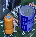
Hi Jared! I've got a pic attached here for ya. But that thing is the exact same color as almost every cap inside a late 70's Technics. The difference is. . . 100v size and epoxy bottom.
A Nichicon KZ might turn in a similar performance, although some "flair" (fletcher muson?) is missing and resolution is lesser.
anatech said:Beyond that, most electrolytic caps have similar performance. You could try capacitors intended for switching power supplies. They are longer and a smaller diameter than normal. They do measure better in the high frequencies. May as well test those out. It's a whole new world!
Keep one thing in mind. There is no magic and everything follows the laws of physics.
-Chris
Hi Chris! I agree with you. Its just that I'd like to see some specifics for those (like me) who put a cap at Ci to avoid DC and then. . . come up with questions.
Do you have in mind some specific models that work nicely in average use?EDIT: Its funny, scary funny. . . I was just thinking orange. Hey, why not? lol!
Attachments
Hi Daniel,
My point was that Marantz and a few other brands used similar capacitor construction. I was pointing out what the differences where for you.
Another capacitor type that has yet to shine brightly are the wet tantalum slug type capacitors. These are nothing like solid tantalum capacitors. They don't even short. Now the best part for marketing types. These are specified for military service and high reliability industrial applications. That is another family type of capacitors for you to dive into. I hope you are paid well, 'cause they ain't cheap.
My suggestion to try switching supply capacitors came from my knowledge of their characteristics. I use some in ..... switching power supplies. I might try some in an amp at some point in time. I'm sure someone must have done this already. Perhaps it's a "shop secret". Any appropriate voltage and capacitance should work. You can install your own epoxy on the bottom, or you can avoid bending the leads and damaging the rubber seal.
My personal favorite type of audio capacitor is almost any film type over electrolytic.
-Chris
Hey Chris, what are the orange caps of Marantz?
I understand some of the Anything comments this way:
Its like any cap could have a good point, and then use it that way. . . like first picking the cap and then adjusting the resistor values to favor its bandwidth? Then, of course, any cap would do, as seen with K50 (common LM1875 kit with crazy resistor values to favor the cheapskate 22uF Nanya).
I like better, the plan of adjusting the resistor values to favor the amp chip and then try to find a cap to match that bandwidth. I see that this must be the "hard way" to do it.
I wonder what the difference is at end result?
Thanks man!
Originally posted by anatech
My suggestion to try switching supply capacitors came from my knowledge of their characteristics. I use some in ..... switching power supplies. I might try some in an amp at some point in time. I'm sure someone must have done this already. Perhaps it's a "shop secret". Any appropriate voltage and capacitance should work. You can install your own epoxy on the bottom, or you can avoid bending the leads and damaging the rubber seal.
There is a thread somewhere arround (I don't remember it's name but it was something like "paralleling film caps with electrolytic caps"), it is one of these great threads that make one feel like if i he didn't knew anything. It was pointed there that low-esr caps like those used in smps were bad for it's use as filters or at other places since ESR it's somehow "good" because it introduces dampening and prevents high Q ressonance peaks in series with wire inductance.
It makes sense to me but i must confess i don't fully understand it.
ionomolo said:
There is a thread somewhere arround (I don't remember it's name but it was something like "paralleling film caps with electrolytic caps"), it is one of these great threads that make one feel like if i he didn't knew anything. It was pointed there that low-esr caps like those used in smps were bad for it's use as filters or at other places since ESR it's somehow "good" because it introduces dampening and prevents high Q ressonance peaks in series with wire inductance.
It makes sense to me but i must confess i don't fully understand it.
I guess that it actually makes good sense to use the cheapskate 100v polyester (plus resistor) for Zobel RC network on amplifier speaker output? Should be more kind to your tweeters than the abrupt hard sounds of MKP?
I think the output Zobel can be formed with any low inductance capacitor. It is a load (the R part) for very high frequency (after passing through the C part).danielwritesbac said:.....100v polyester (plus resistor) for Zobel RC network on amplifier speaker output? Should be more kind to your tweeters than the abrupt hard sounds of MKP?
The purpose of the Zobel load is to improve stability. It also serves to attenuate back EMF and RF coming from the speaker.
To me it seems that MKS, MKT, MKP will all work equally well here and are unlikely to be audible if correctly sized.
The zobel illustrated in LM3886.pdf is strongly audible on MKP, but not on the cheapest possible polyester cap of the same (or even twice as much) capacitance value.
You caught me!
The problem is that everyone insists on 2.7R for the zobel.
So, I was trying to sneak in a different resistance value--inside the capacitor that costs 4x less.
(and no more boring gray color).
You caught me!
The problem is that everyone insists on 2.7R for the zobel.
So, I was trying to sneak in a different resistance value--inside the capacitor that costs 4x less.
(and no more boring gray color).
Hi Daniel,
stick a capacitor across the output, particularly without a Zobel to load the amp and you are moving the phase margin towards instability.
This is virtually guaranteed to be audible and will be worse, the better the capacitor.
You are probably hearing the difference between more/less overshoot on transient signals with the better/worse cap.
Start understanding what you are experimenting with before you mislead us any more.
Maybe plain english would be easier to understand.So, I was trying to sneak in a different resistance value--inside the capacitor that costs 4x less.
I have a view, but no data to support it, that National's recommended 2r7 is a bit low for the HF load in the Zobel. I would recommend experimenting with 3r9 to 8r1 as a more usable range for the output Zobel resistor.
My reasoning for this:- if the amp is designed to drive an 8ohm load without overstressing the output stage then why add a 2r7 load in parallel to absorb the HF oscillation. A very low load like this(8ohm//2r7) is quite likely to exacerbate stability tendencies, particularly if further (crossover+cable) capacitance is also parallel to the load.
AndrewT said:I have a view, but no data to support it, that National's recommended 2r7 is a bit low for the HF load in the Zobel.
Well, I couldn't convince anybody about that either.
EDIT: But, isn't the approximately correct figure more like 4R if using polypro (boring gray square MKP)?
agreed.ionomolo said:Thought-provoking threads should only be read by people who want to think.
Ci yet again still ...
Just a couple of random thoughts ...
The voltage across Ci is going to be on the order of the voltage at the input, so rating is almost irrelevant. If one objects to reverse-biasing an electro even at these low voltages, modern low-voltage bipolars are quite compact. Moreover, Doug Self mentions that the dreaded "electrolytic distortion" is much lower in bipolars. So instead of trying to put a One Farad Supercap in there (computer grade, of course; the computer uses it to remember its settings), a bipolar in the 10-22 uF range should produce good results.
Has anyone tried tantalum there? According to the catalogs, modern tantalums are much more reliable than those of even a decade ago. Another development is the "organic aluminum" something-or-other-for-an-extra-buck, which claims to improve both ESR and durability over standard wet electros. Anybody have any experience with them?
- Status
- This old topic is closed. If you want to reopen this topic, contact a moderator using the "Report Post" button.
- Home
- Amplifiers
- Chip Amps
- gainclone dissapointment