details on my batteries etc
Batteries are yuasa sealed lead acid 7AH. At present I have one central battery supply + & - 24 Volts
for quite a while I was using two 3875's per channel balanced working with + and - 12v per chip and separate supplies.
going to + & - 24v with a central supply was better. In balanced mode I had one 10,000uf T network cap across + & - rails with a resistor divider & cap to give me an input ground.
Now I have gone over to unbalanced working to drive some low impedance speakers. I now think that one chip per channel is probably the ideal arrangment.
The T networks are still across the rails one in each amp and there is 1000uf elna RSH between earth and the neg rail to keep earth HF impedence low.
If I was starting from scratch it probably would be different but this arrangment just evolved with time and seems to work very well
On the amp I made with the tranformers & chokes there was a central supply with one choke per channel there and another in each of the amps.
hope that is not to confusing
mike
Have you read what I said??!
Yes Carlos - but obviously not very carefully.

My apologies.
lieven
Putting caps in parallel will lower the impedence but will not necessarily bring about the best ESR. Keep in mind that the more caps you have in parallel, the more inductance you will introduce. Check this out for a more thorough explanation.try 8 different brand 220 microfarad paralleled.
nania said:Keep in mind that the more caps you have in parallel, the more inductance you will introduce.
That is completely wrong! Every doubling of the number of caps will halve the inductance; the limiting factor becomes the inductance of the bus bars. If constructed of large sheets of copper their inductance will be quite low indeed and practical reduction of ESL will extend to 10-20 caps in parallel or more. I've never attempted to measure this but consider that conventional ground planes have quite low impedance to many MHz.
At any rate the inductance can never INCREASE if you add a cap and change nothing else.

tiroth
lieven
tiroths reply to my post exemplifies energy lost in chaos better than your suggestion. Build your gainclones as you like and pay me no further heed, it's obvious that I know nothing
I would be hesitant to make such a bold statement without measuring first but horses for courses I guess...That is completely wrong! Every doubling of the number of caps will halve the inductance
lieven
tiroths reply to my post exemplifies energy lost in chaos better than your suggestion. Build your gainclones as you like and pay me no further heed, it's obvious that I know nothing
There is no need to measure.nania said:tiroth I would be hesitant to make such a bold statement without measuring first but horses for courses I guess...
parallel caps
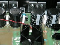
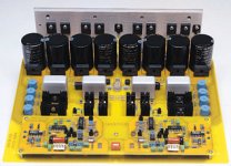
Caps in parallel lower inductance and ESR. This is so commonly done in high end audio. I have lost count of the number of times I have seen it done. Short wide PCB traces will give resistive and inductive parasitics lower than those of many electrolytic filter capacitors. Mounting smaller caps very close to the output devices with low impedance grounds to the central ground node is a popular technique. This bypasses wiring and cap inductance from the main filter caps. I don't know why this isn't a no brainier to anyone with some knowledge about capacitance and inductance.
Caps in parallel lower inductance and ESR. This is so commonly done in high end audio. I have lost count of the number of times I have seen it done. Short wide PCB traces will give resistive and inductive parasitics lower than those of many electrolytic filter capacitors. Mounting smaller caps very close to the output devices with low impedance grounds to the central ground node is a popular technique. This bypasses wiring and cap inductance from the main filter caps. I don't know why this isn't a no brainier to anyone with some knowledge about capacitance and inductance.
Attachments
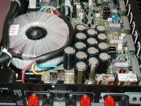
Another example
McCormack Audio Amp. The DNA in the product name is for distributed node amplifier and refers the putting the filter caps close to the output devices.
http://www.mccormackaudio.com/index1.html
From :
http://www.audaud.com/audaud/SEP01/EQUIP/equip2SEP01.html
"Knowing that McCormack is now a subsidiary of conrad-johnson, when the DNA-225 arrived, I was curious to see what the impact of the new ownership would be on the Steve McCormack designed components. After all, Steve had been making amps and preamps long before being acquired by c-j, and his designs have a signature-style power supply: The Distributed Node Amplifier supply. This supply is distinctive in that it does not use the large soup can type capacitors in the power supply, nor does it cluster the supply caps around the input transformer. What Steve has done, starting way back with his DNA-1 in the middle 1990's, is locate the supply caps (smaller ones) right next to the bipolar output devices. That way, when the output device needs extra energy it has a low resistance source right next to it."
Attachments
and yet another one
The DMA-150 High Resolution Amplifier from Spectral Audio
http://www.spectralaudio.com/dma-150.htm
I think someones knowledge about transformers extends to the subject of capacitors as well..........
The DMA-150 High Resolution Amplifier from Spectral Audio
http://www.spectralaudio.com/dma-150.htm
I think someones knowledge about transformers extends to the subject of capacitors as well..........
Attachments
Fred Dieckmann
Yes, inducters in parallel will behave as resistors in parallel but this is parasitic inductance which is part of the capacitor and its rule is not so simple particularly when the capacitors have different (non-linear) ouput curves. I say it might be worth a measure or two before making blanket statements but as I said earlier, the forum may choose the methodology that suits them. As for my knowledge of transformers, fortunately, it grows daily even without your contribution. Nice pictures.
Yes, inducters in parallel will behave as resistors in parallel but this is parasitic inductance which is part of the capacitor and its rule is not so simple particularly when the capacitors have different (non-linear) ouput curves. I say it might be worth a measure or two before making blanket statements but as I said earlier, the forum may choose the methodology that suits them. As for my knowledge of transformers, fortunately, it grows daily even without your contribution. Nice pictures.
Very nice pictures
Fred, some good pictures you've put here.
I totally agree with you.
After all, if people would read some op-amp datasheets, it's all there.
It's always recommended to bypass near the devices' supply pins with small caps.
I'm amazed people reporting bad results with Gainclones and big caps...
I'm going to test that, I don't know yet if it's true, but of course I won't take out the 0.1uf poly caps I have very near the supply pins of the LM3875s (one goes from + to - pins, the other two go from + to ground and - to ground).
And the 1000uf caps will always be there on the circuit too.
I'll just test adding some bigger caps before the circuit and then listen.
And what's more, if you bypass a big cap with a smaller one of other type (poly, ceramics...) you're taking the advantages of the two of them.
As an example, I once saw some a graphs of the impedance vs frequency of two types of caps: tantalum and ceramics.
Tantalums have low impedance at low frequencies, and then impedance rises.
Ceramics have high impedance at low frequencies, and low impedance at high freq.
A third graph showed the impedance curve of that 10uf tantalum bypassed with the 0.1uf ceramics: a line with low impedance and almost straight.
This is just an example of what you can do with different caps.
I have heard reports from some experienced audio DIY types that by capacitor passing sounds awful and should be avoided at all costs.
my guess is that in some applications it might create problems. I would tend to proceed with caution and keep listening carefully.
Are Slit Foil caps available in countries other than the UK ?
The idea is to slit the plates thus producing the effect of many many small caps rather than one big one. In the T network Caps, that I am using at present, this is combined with the 4 terminal arrangment where the current has to pass along the length of the plates on route to and from the load.
...very nice
Has anyone done any comparisons between these T network Caps and the black gate BG or panasonic FC ( hope I have those names correct ) or will I be doing an original piece of research ?
cheers
mike
my guess is that in some applications it might create problems. I would tend to proceed with caution and keep listening carefully.
Are Slit Foil caps available in countries other than the UK ?
The idea is to slit the plates thus producing the effect of many many small caps rather than one big one. In the T network Caps, that I am using at present, this is combined with the 4 terminal arrangment where the current has to pass along the length of the plates on route to and from the load.
...very niceHas anyone done any comparisons between these T network Caps and the black gate BG or panasonic FC ( hope I have those names correct ) or will I be doing an original piece of research ?
cheers
mike
Still confused!
"Yes, inductors in parallel will behave as resistors in parallel but this is parasitic inductance which is part of the capacitor and its rule is not so simple particularly when the capacitors have different [nonlinear) output curves."
Inductance is not a non linear impedance but is measurable value resulting from the winding geometry of the capacitor. The series impedance parasitics the cap can be modeled by a series RCL. The R value is the ESR value of the cap. The inductance figure or the cap's impedance curve is often given by the manufacturer. This not mysterious as some would have you believe, but is very straight forward.
http://www.chemi-con.com/u7002/characteristics.php
two years ago on the venge of small caps better I replaced the one 47000mf cap x channel of my Bel 1001 amp mk2 with ten 4700mf then few more small electrolitcs and then 10mf polyprop down to 0,47mf film caps. The Bel is always been very fast and precise so I thought I bettered it with the new PS.
To my surprise the amp lost much of the transient speed and punch in the low
without acquiring anything in the mid-high. So I started to take off the smallest caps and so on till I put back the big cans and it returned the beautiful amp it was. A diy failure is not easy to admit but my hears talked clearly. Differently story with rectifiers I replaced the standard bridge with soft recovery diodes and that was a pretty big jump.
Giorgio
Fred Dieckmann
So is tiroth correct when he states that the inductance effect of a capacitor bank always halves each time you double the number of caps? Seems a simple enough concept not to confuse anyone simple but why doesn't it hold up in practice?
Let's go through the logic, shall we?
A lower ESL/ESR is sonically desirable, correct? According to your hard and fast rule, more caps in parallel will sound better and yet, they somehow manage to sound worse. How do I know this? I made an inverted gainclone with a 16x220uF supply configuration and compared it to the recommended setup; the soundstage shrunk, flattened and fuzzied. I should add that the music got fat in the midtones and seemed to lose its immediacy as well. The caps tested were all unused and from the same family (Panasonic FC). Hmmm, what do we attribute all of this degradation to? Mismatched caps, poor soldering? Perhaps, just perhaps, there may be something increasing the effect of the inductance on the energy delivery when more caps are introduced. Something like phase/pulse energy delivery deviations due to rising INDUCTANCE effects when there are too many caps in parallel. Simplicity says this is impossible because we should have lower inductance when inductance is paralleled and therefore the effect should be smaller, right? Ask the people who have built the inverted gainclone with more and larger caps to hear what they got as a result before you go looking for ways to attack me and my threads. Its not that I mind riling you up, I really think you do the most good when you have a target to snipe at, I just wish you'd put the same energy into the transformer thread where it might really be helpful
Maybe you meant to say that your post was "for no brainers"
Nania, you are taking quite an intuitive leap when you say
More caps in gainclone sounds bad
=>
The ESL is higher
You can debate all day about the "measurability" of audio phenomena, but we're talking about a simple physics concept here. Caps in parallel halve ESR and ESL, provided the parasitics << final values. This is simply a fact. Note that I've said absolutely nothing about the sound!
If you want to look for boogeymen feel free to consider resonances, euphonics, conduction angles, etc. We have enough things which are difficult to measure/account for without introducing suspicion of how resistors and inductors add up.
Star Treck math
" Something like phase/pulse energy delivery deviations due to rising INDUCTANCE effects when there are too many caps in parallel."
No...............
Inductors in parallell give an effective inductance as follows:
1/L = 1/L1 + 1/L2 + 1/L3 + .......
Also for two inductors in parallel:
for those that really want to understand impedance:
http://hyperphysics.phy-astr.gsu.edu/hbase/electric/impcom.html#c1
http://hyperphysics.phy-astr.gsu.edu/hbase/electric/imped.html#c2
You have to start with fundamentals to discuss more complicated circuits. There are factors such as grounding and the lead/ trace inductance from the caps to the supply terminals. Try a pair 220uF as close to the IC as you can get them in combination with the 1000uF filter caps. You really should be using 0.1 uF film decoupling caps right at the IC. Black Gate caps do not work well with film bypass caps. This is probably due to their due to their very low ESR. I have used them with similar values in parallel before with good results.
The ideal is not to throw all theory out the window but to investigate why things sound different. Inventing wild theories will not get you there. Good sonics and good engineering are not as counterintuitive as some would like to believe.
"I really think you do the most good when you have a target to snipe at, I just wish you'd put the same energy into the transformer thread where it might really be helpful"
I guess understanding inductance would be a good idea when talking about transformers. I have already contributed enough to that thread. Surely someone else will have some contributions if it is an interesting topic with relevant questions presented. Why don't you ask about what you're most curious about if you want to revive that thread?
- Status
- This old topic is closed. If you want to reopen this topic, contact a moderator using the "Report Post" button.
- Home
- Amplifiers
- Chip Amps
- Gainclone Cap Survey