jean-paul said:www.acoustic-dimension.com is not very expensive with BG's.
Nichicon PL is not the finest sounding around, Panasonic FC is much better.
Have you tried the Nichicon HE Series, which is catagorized as having an "extremely low impedence"?
Digikey just started carrying most of the Nichicon line.
--
Brian
BrianGT said:
Digikey just started carrying most of the Nichicon line.
Do you have any more info on this? All I can find by their search function is the HE, PW, UD, VR, VZ, WT, WX series. Still no Muse

leadbelly said:
Do you have any more info on this? All I can find by their search function is the HE, PW, UD, VR, VZ, WT, WX series. Still no Muse
The following are all Muse Series
KZ, FG, FX, SK, SW, MC, VK, ES.
I have used the ES Bipolar and the KZ which is thier best Audio Cap, with good results. I have attached a little spreadsheet for reference.
Regards
Anthony
Attachments
Bas Horneman said:Any suggestions for replacement capacitors...
BrianGT said:
Have you tried the Nichicon HE Series
Coulomb said:
I have used the ES Bipolar and the KZ which is thier best Audio Cap, with good results.
I did comparison test today between Panasonic FC, Nichicon Muse and BG STD.
Panasonic sounded pretty well overall. Comparing to BG they didn't have the extention in highs, that air that some like. Also, the bass was much better with BG (the punch). However, BG seemed to be more etched and careful system maching is required in order to avoid excessive brightness. BG were more direct, while Panasonic sounded somewhat laid back and recessed. But one can listen for hours to Panasonics and not get tired. With BG it's a mixed bag. They might impress initially but later _may_ become fatiguing. But all three of us, listening, preferred BG by quite a margin. Which doesn't mean Panasonics are not good. They are actually very good and some might actually prefer them.
Now, regarding Nichicon Muse, we didn't like them at all. They were too laid back and not involving at all, almost like a curtain was thrown over the soundstage. I much more preferred Panasonics, Nichicons were laid back even more than Panasonics and somehow were lacking any presence.
how did your cat go out?
moral of the story don't let your cat drink coffee!!!!! the reaction can be harmfull!
matjans said:This was right after the same cat tipped over my first cup of coffee of the day, of course.

moral of the story don't let your cat drink coffee!!!!! the reaction can be harmfull!
Peter,Peter Daniel said:
I did comparison test today between Panasonic FC, Nichicon Muse and BG STD.
Did you get a chance to try the Nichicons I gave you?
Peter Daniel said:After finding Muse not that good (at least to us), we didn't even proceed with those, but I will try them soon, maybe tomorrow?")
Peter how much current were you pulling from them and at what voltage? Did you manage to measure the impact they had electrically in your tests?
I wonder if one comparisson under one set of conditions is enough to rate any component. What would the Panasonics sound like in a high demand circuit? I know the Panasonics work well in my Sub Amps and have greatly improved the viceral impact of the low notes.
Regards
Anthony
We didn't have any measuring equipment, so we didn't measure
But we were listening (at normal levels), 34V rails, caps rated 1000u/50V. This is enough good test for me. The Nichicons didn't sound special in any way, simply uninvolving and somewhat blank. That's about all.
If you are into deep bass (and slam), BGs are definitely your ticket.
PS: I didn't rate any components, I just described my observations. You might make your own and compare if they are in line with mine
Also note that those were only 1000u caps per rail. I believe your sub amps have somewhat more capacitance. With such small capacitance the type of cap makes bigger difference (in the viceral impact ).
The Piltron transformers delivered to my house yesterday. This time I have ordered two 20-0-20 400VA shielded for the two kits that I bought (one transformer for 2 channels). In the thought process of assembling the chassis at the moment base on the size of the transformer.
I noticed the way Brian mount the amp boards as illustrated in his manual that I am not 100% sure that is the best way to mount the amp boards to the bottom of the chassis and the chip mount to the side. If there is a slight deviation from 90 degree of the chip and board, and also the side panel with the bottom panel; the chip mounting height on the board in relation to the three holes drilled, one for the chip two for the stand offs. It will stress all the pins of the chip and the solder joints wouldn't it?
Is there a better way? What about mounting all three points to the same plane using an L shape stand off?
My intension is not to install a switch but just a fuse with the assumption that the GC draw little current when at idle. Is this ok?
Also I have asked the qusetion in another thread regarding the shielded transformer I will ask again here; Is there any preference way to connect the shielded lead from the transformer?
Thanks in advance,
Chris
Cappy said:Could someone remind me if the Blackgate 1000 uF caps will fit on Brian's PC boards that we were sent.
I seem to recall someone (Peter?) saying they won't fit until the board is reworked but I can't find reference to this in a search.
Thanks.
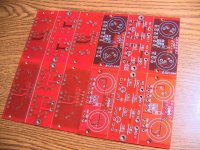
The initial boards that I had made did not have the proper spacing for the BG capacitors, but I had a new batch of boards made with the spacing for the BG capacitors. For the initial group order, people were given a choice of the boards. Most of the kits shipped out with the old boards, unless requested. Most of the pcb sets shipped out with the new boards.
The current pcbs that I have on hand will work with the larger BG STD 1000uF capacitors, which Peter is referring to.
Here is a picture of the 2 board revisions, with the front one being the old board set, and the back one being the new board set. I ordered them all from the same board house, but the first batch was contracted out to another board house, so it has a different appearance. I am guessing that it was plated before the solder mask was applied, and the latest board was just the opposite.
--
Brian
Attachments
You can still use BG with initial boards, if you mount BG on the other side and drill additional hole (and open the existing one).
If you intend to use GC just for the bass, you might try more capacitance, but I wouldn't go over 4,700u. In the full range, 1,500 or so , seem to work the best, as anything more somehow veils the sonics and makes the amp sound more like your average SS piece. Carlos was at one time into higer capacitance and he didn't want to listen about smaller values, but eventually he also "found the truth"
To Chris ma: Mounting this way wil not cause any stress on the chip, as the pins are pretty long, so they provide quite a lot of flexibility and free play. Using additional brackets under the chip, lowers the efficiency of heat transfer (if this is an issue at all). As to shielding, I had chip mounted directly at the transformer (no shield at all) and apparently it was not a problem.
It seems like the board is pretty well designed, and chip is rather stable. It also sounds surprisingly good
chris ma said:The Piltron transformers delivered to my house yesterday. This time I have ordered two 20-0-20 400VA shielded for the two kits that I bought (one transformer for 2 channels). In the thought process of assembling the chassis at the moment base on the size of the transformer.
I noticed the way Brian mount the amp boards as illustrated in his manual that I am not 100% sure that is the best way to mount the amp boards to the bottom of the chassis and the chip mount to the side. If there is a slight deviation from 90 degree of the chip and board, and also the side panel with the bottom panel; the chip mounting height on the board in relation to the three holes drilled, one for the chip two for the stand offs. It will stress all the pins of the chip and the solder joints wouldn't it?
Is there a better way? What about mounting all three points to the same plane using an L shape stand off?
My intension is not to install a switch but just a fuse with the assumption that the GC draw little current when at idle. Is this ok?
Also I have asked the qusetion in another thread regarding the shielded transformer I will ask again here; Is there any preference way to connect the shielded lead from the transformer?
Thanks in advance,
Chris
As the common accepted practise is a star ground this would be the best place to connect the shield.
Regards
Anthony
- Status
- This old topic is closed. If you want to reopen this topic, contact a moderator using the "Report Post" button.
- Home
- Amplifiers
- Chip Amps
- Gainclone building thread based on BrianGT's boards