amplifierguru said:Hi Benson,
Your Q1,9,10,11 don't do anything. You don't need them.
R11,12 are best removed (anytime) as they just waste gain which could be used for NFB and increase modulation (distortion). They're a hangover from the TIM dreaming.
NFB from the output corrects the worst ERRORS in most amplifiers - the output stage ones. You don't wan't to be listening to these as Thanh says. And they're load dependent so variable.
Cheers,
Greg
Hi Guru,
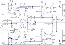
I think this is the four'th time any one says these aren't necesary. Please take a good look at the shematic. Together with R48 and R49, they form a diff VAS.
See post#8
http://www.diyaudio.com/forums/showthread.php?postid=799378#post799378
In the attachment, you can see the latest version (NFB).
Attachments
Hi Everybody !
I made a PCB for a sysmetry amp . Then I converted it to Blameless . I tried to dont' use feedback for all stage . I took feedback from the previous output stage . The result show a bad sound . Then I converted Blameless to Symasym5 . While I did it , i found that iq of Blameless was only 2mA . I think that this is a reason why the sound was bad . I'm using Symsym5 with cascode input,triple darlington output . Again ,I dont use global feedback ,and iq for output stage is 34 mA . The result show a good sound .
I'm sorry about the my previous post
I made a PCB for a sysmetry amp . Then I converted it to Blameless . I tried to dont' use feedback for all stage . I took feedback from the previous output stage . The result show a bad sound . Then I converted Blameless to Symasym5 . While I did it , i found that iq of Blameless was only 2mA
. I think that this is a reason why the sound was bad . I'm using Symsym5 with cascode input,triple darlington output . Again ,I dont use global feedback ,and iq for output stage is 34 mA . The result show a good sound . I'm sorry about the my previous post
amplifierguru said:Hi Benson,
Your Q1,9,10,11 don't do anything. You don't need them.
Cheers,
Greg
Benson has already answered.
But this misreading of schematic has to do with voltage supply being to the left.
And resistor feeding VAS in horisontal.
We are not used to this.
I answered this in post #7 and Benson in post #8.
-------------------------------------------
Post #7 by lineup:
Looks like that, at first sight.
But if you look at power supply - to the left -
you see VAS is a differential stage.
With a common resistor from supply.
about non-switching output stage
http://www.diyaudio.com/forums/showthread.php?postid=282339#post282339
Look at Tanaka' schematic , http://www.diyaudio.com/forums/attachment.php?s=&postid=298067&stamp=1073559140
http://www.diyaudio.com/forums/showthread.php?postid=282339#post282339
Look at Tanaka' schematic , http://www.diyaudio.com/forums/attachment.php?s=&postid=298067&stamp=1073559140
thanh said:Hi Everybody !
I tried to dont' use feedback for all stage . I took feedback from the previous output stage . Again ,I dont use global feedback ,and iq for output stage is 34 mA . The result show a good sound .
Thanh,
The worst distortion in an amp is comming from the output section, isn't it? You are taken NFB from the drivers, as I can understand out of your explanation?
The idea about the non-switching output stage looks very interesting, but I will not use this. I don't have enough experience to integrate this into my amp. Maybe in another project in the future?
Thanks
Ben
Hi all,
I implanted a pot (P1) in one of the current sources for the cascoding diodes of the diff pairs. With this I can trim the DC-offset to a minimum. Works great in sim.
For connecting the DC-servo, I would like to use the "midpoint" of both the diff pairs. In serie with a 3K9 resistor is the dc-servo connected.
The dc-servo circuit is here presented by "V7". If I set V7 at 13V --> the output offset is +-1.4Vdc. I think this is enough, not?? The opamp has to deliver then +-3.7mA.
What do think about this method? Please be critical.
Best wishes for 2006
Attachments
I haven't much knowlegde about symmetry amp with jfet . You can refer to this site http://www.ne.jp/asahi/evo/amp/J200K1529/report.htm
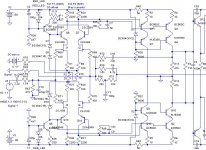
I also haven't skill at non-switching output stage . I only try to simulate with some value which Steven suggested .
I tried to use this topo for symasym5 but output tst still stop . Oh ! I need to re-check
I also haven't skill at non-switching output stage . I only try to simulate with some value which Steven suggested
.I tried to use this topo for symasym5 but output tst still stop . Oh ! I need to re-check
Attachments
ah ! I have also just converted symasym5 to symmetrical amp .Good ! Blameless and Symasym5 became bad after were used for a long time . I dont' know what reason is . I used 2N5551Y to build those amp . I always mod amp . Because I'm a man which have techique tendency . A symmetry girls is always a beautiful girl . Current mirror seem to be a good method can kill distortion but It seem to be unstable . I'm a EE . My knowlegde can't solve occsillate problem well .
. Current mirror seem to be a good method can kill distortion but It seem to be unstable . I'm a EE . My knowlegde can't solve occsillate problem well .Upupa Epops said:And one important notice : rail voltage at VAS must " flow " on output's rail voltage, so all PSs must be connected at series...
Pavel,
Are you really sure that this is correct with my topology? When I hold the front stage (diff + VAS) at 82V, and lower the power supply voltage for the output FET's to 65V, THD stays +- the same in a simulation.
I would like to use a fixed voltage there, because my diff pairs aren't coupled with a CCS.
Greetz
Ben
djk said:"rail voltage at VAS must " flow " on output's rail voltage"
So it picks up all the ripple and noise on the main supply, no thanks. I run the front end off a different supply, do what you like.
I prefer often two separate voltage supply.
Best if is BOTH input and output stage supply voltage stay stable.
Most of all I want a steady (regulated) supply for input and VAS stage.
Because they control what happens at output, using feedback,
and should not be allowed to be effected by the output, and eventual fluctuations in output stage supply voltage.
Input differential is the heart of amplifier.
It should have best and clean current as possible!
The practice to use SAME supply= same Trafo for everything in a power amplifier is, as I see it bad,
and comes from amplifier mass industry.
Here we can save 1 little trafo and make it cheap and more simple and so make more money.
Trafo for input/VAS can be very small, 5-20VA, does not cost very much.
This is the correct way to build power amplifiers.
It is not the most cheap and simple but the way that I prefer.
To let input/VAS supply 'follow' output supply may be a good choice in some amplifier topology
but I would say this is not often.
To me, is very obvious,
that it is no good letting VAS transistors go to a few volts form clipping,
compared to let them have 10 Volts more headroom
for doing their important work.
I simply can not understand practice to feed them from output stage.
Of course they will benefit from having a clean supply
that has a very good margin to saturation.
We see often they try to filter from output supply with resistors + capacitors in rail
and so get a more clean current for input.
This means VAS get a little bit lower voltage than output - CRAZY!
The very existens of these resistors+capacitors in supply rails,
show there is something wrong - something not optimal.
Clean current as possible...
My mosfet amplifier with this topology have SNR ( ref to 1 V input ) more than 124 dB ( IHF - A ) and 120 dB ( linear ) - do you need more ? Distortion is around 0.001 %....
Only this topology give you perfect stability by clipping...but it is long talking....
My mosfet amplifier with this topology have SNR ( ref to 1 V input ) more than 124 dB ( IHF - A ) and 120 dB ( linear ) - do you need more ? Distortion is around 0.001 %....
Only this topology give you perfect stability by clipping...but it is long talking....
- Status
- This old topic is closed. If you want to reopen this topic, contact a moderator using the "Report Post" button.
- Home
- Amplifiers
- Solid State
- Fully complementary FET-in FET-out design