
Also, how critical is the value of the output cap? I have 3uf or 12uf caps (the 12uf caps being on the "large" side). Any suggestions there?
The choice of output cap value depends on what you expect the preamp will be driving.
Commercial solid state power amps often have an input impedance as low as 10k ohms. If you do the figuring, in order to get a low frequency response of -3dB at 3Hz, you'd need 5uF as the output cap if it's driving an amp with 10k input impedance.
If you use the 3uF cap and a solid state amp with 10k ohm input impedance, the frequency response will be -3dB at about 5Hz. That's probably fine.
If the preamp will only ever drive a tube amp with input impedance of 100k ohm (or higher), then 0.5uF (500nF) would give you -3dB at 3Hz.
Here's an online calculator for that:
(Sample)RC Low-pass Filter Design Tool - Result -
--
Last edited:
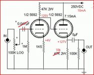
Not many people understand how the CF output stage bias works when is direct coupled from the input stage. This direct coupled topology is used for the distortion it creates in many guitar amps. For Hi-Fi I'd certainly have the cap. I wouldn't try to drive any load less than 10k ohms with this circuit.
Further, I think the 6SN7 is more linear when it's got about 7mA per triode at quiesence. This circuit runs them rather low current.
If you really want to improve the linearity, I'd recommend replacing the plate resistor of the first triode with a constant current source (or sink). That improves linearity and power supply hum and noise rejection. You can also replace the larger cathode R on the CF stage with a CCS as well, for the same reason.
Linearity is already quite good, linear tube + not decoupled cathode resistor.Fora cathode follower linearity isn't much of an issue.Not many people understand how the CF output stage bias works when is direct coupled from the input stage. This direct coupled topology is used for the distortion it creates in many guitar amps. For Hi-Fi I'd certainly have the cap. I wouldn't try to drive any load less than 10k ohms with this circuit.
Further, I think the 6SN7 is more linear when it's got about 7mA per triode at quiesence. This circuit runs them rather low current.
If you really want to improve the linearity, I'd recommend replacing the plate resistor of the first triode with a constant current source (or sink). That improves linearity and power supply hum and noise rejection. You can also replace the larger cathode R on the CF stage with a CCS as well, for the same reason.
With CCS's the gain (now around 11x) goes up to over 15x, probably to much and the drive capacity goes up.Is there a need for ?
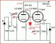
If the supply is present before tube is hot there is the supply voltage between the grid and cathode of the follower, not healty.In that case a diode is advised.In normal operation the diode stays reverse baised.
Mona
Attachments
I see.. so basically this circuit simply cannot be used for headphones. Correct?
Inviato dal mio GT-I9301I utilizzando Tapatalk
Correct.
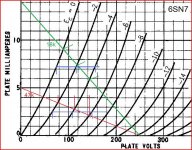
The output impedance of a cathode follower can be approximated by 1 divided by the transconductance or 'slope' (Gm) of the tube, at the operating point at which that cathode follower is being used.
That formula would be written:
1/Gm
The Gm of the tube is expressed in milliamperes per volt, or mA/V. When you do the 1/Gm equation you'll use amperes, so 5mA would be 0.005 ampere (0.005A).
What's the Gm of a 6SN7 with about 125V on the plate and 5mA plate current? According to the data sheet, it's about 2.3mA/V. So...
1/0.0023A = 434.8 ohms
The output impedance of a 6SN7 cathode follower at these operating points is about 435 ohms.
For an amplifier, you want the output impedance of the amplifier to be at least half the load impedance. This ratio of source impedance to load impedance is called the 'damping factor' of the amplifier.
In this case, the load is your headphones. For a damping factor of 2 (2x smaller in value than the load impedance) with your 32 ohm headphones, you'd want the output impedance to be no higher than about 16 ohms (at the very highest).
As we saw earlier, the output impedance of the 6SN7 cathode follower with these operating points is over 400 ohms.
No, this will never work for driving your headphones. You may get a noise out of it, but it won't be any kind of 'accurate reproduction.'
--
Last edited:
but a mosfet follower fed with around 48v and capacitor coupled to the output stage would effectively provide any current needed for headphone use whilst contributing little to none to the sonic qualities of the preamp. I was thinking of an irf610 biased to 150mA with a large 150uf-200uf cap before the output.


If going through all that effort I would replace the cathode follower with an IRF820 too ")
One less tube, better drive capability. You still need an out cap unless you're clever and do a DC servo.
Even better- cut the supply voltage in half and use a 6N16B, now the whole circuit is the size of a saltine cracker
One less tube, better drive capability. You still need an out cap unless you're clever and do a DC servo.
Even better- cut the supply voltage in half and use a 6N16B, now the whole circuit is the size of a saltine cracker
Last edited:
Alright, now what if I suggested doing something considered heretical and put a CCS on that cathode follower in addition to removing the cap?
A proper CCS can be recommended for almost any high-end CF application.
And yes, do remove the coupling cap and its associated resistor. Two fewer parts is a good thing. I do not get why people argue that point. Nearly every Audio Research amp and preamp since 1970 has used directly-coupled CFs.
If going through all that effort I would replace the cathode follower with an IRF820 too
One less tube, better drive capability. You still need an out cap unless you're clever and do a DC servo.
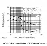
Use MOSFET followers on tube plates with caution. You are loading the preceding plate (a high impedance node) with the non-linear gate capacitance of the MOSFET, creating the potential for phase intermodulation distortion. If you need a MOSFET to drive, say, headphones, consider bootstrapping that MOSFET with another MOSFET a la Allen Wright’s CFs. That reduces the capacitance seen by the preceding tube, but then it gets complicated.
Unless you’re driving a headphone or hundreds of feet of cable, stick with CFs if you’re going to the trouble of using tubes in the first place. Just my two pesos...
Attachments
- Status
- This old topic is closed. If you want to reopen this topic, contact a moderator using the "Report Post" button.
- Home
- Amplifiers
- Tubes / Valves
- Frrank's 6Sn7 preamp...take out coupling cap??