I suggest that if you have built a regulated supply where you could still hear the difference between tube vs SS rectifier, then find a better regulator.
Not necessarily. Consider, for example, a poorly filtered heater supply with switching artifacts coupled into it from sharing a core with the HV windings. The heaters then cheerfully couple these spikes into the cathodes of the signal tubes.
Or poor grounding, where switching spikes are induced into the signal circuit.
There's lots of ways that poor engineering and execution can make differences between tube and SS regulation audible.
SY said:There's lots of ways that poor engineering and execution can make differences between tube and SS regulation audible.
I assume you mean rectification instead of regulation? If not, I'm not sure I get your drift.
Alex Kitic said:You know, some people seem to prefer SS diodes. I am comfortable with that, some like blonds and some brunettes... but not hearing any difference? There must be something wrong with that setup.
Here are the projects I did:
Vixen Main Schemo
Vixen Main PS
Le Renard Main Schemo
LR Main PS
For both projects, I used a semi-star construction with circuit boards made semi-dead bug style. Each subsystem circuit board was insulated from the metal chassis, and had its own connection from the local ground plane to the DC neutral. This keeps any residual AC ripple out of the signal path quite effectively, and there is very little residual AC hum at the output. Maybe a few millivolts which you can barely hear.
The only difference is that I never installed the Zeners shown in the Le Renard schemo since I discovered that I didn't need to ground the AC heater winding to get a very quiet amp. Otherwise you'd need 'em to avoid exceeding the Vhk rating of the 6FQ7 on power up.
Yes, it is blondes and brunettes -- the amps are just too complicated for my taste (and PP).
The grounding has very little to do with the fact whether you can or cannot hear the difference between solid state and tube rectification.
Maybe you cannot hear differences between cables?
I don't think we are discussing poor engineering and/or execution. We are discussing whether one can or cannot hear the difference between tube rectifiers and SS diodes... and I am quite perplexed that there are people who listen to music, and build amps... but cannot hear this type of difference in the resulting sound which is not at all subtle.
The grounding has very little to do with the fact whether you can or cannot hear the difference between solid state and tube rectification.
Maybe you cannot hear differences between cables?
There's lots of ways that poor engineering and execution can make differences between tube and SS _______ audible.
I don't think we are discussing poor engineering and/or execution. We are discussing whether one can or cannot hear the difference between tube rectifiers and SS diodes... and I am quite perplexed that there are people who listen to music, and build amps... but cannot hear this type of difference in the resulting sound which is not at all subtle.
Funny. I was looking for a simple preamp for a small integrated amp I was building- I wanted to use a 6CG7 (6SN7 exact equivalent in miniature bottle).
Just played around in TubeCad... and damn if I didn't come up with just about the exact same values as Frank's preamp. Didn't even see this post until I had built two units with the design I came up with.
On my preamp, I wound up decreasing the gain a bit (using a 22K 2w resistor instead of a 47K 2w) due to the large amount of gain in the amp section... but otherwise, it's the same values. I can say- this design (at least those gain stage values) works VERY well!
Regards,
Gordon.
")
GordonW said:Just played around in TubeCad... and damn if I didn't come up with just about the exact same values as Frank's preamp. Didn't even see this post until I had built two units with the design I came up with.
Cool!
On my preamp, I wound up decreasing the gain a bit (using a 22K 2w resistor instead of a 47K 2w) due to the large amount of gain in the amp section... but otherwise, it's the same values. I can say- this design (at least those gain stage values) works VERY well!
Regards,
Gordon.
I was thinking about the gain and would like it to mate well with Pass A40 monoblocks. Six foot coax cable from from Preamp to each mono block amp. Any knowlege what would work best?
Cheers
What's input impedance on the Pass A40s? I'd think that if it was 100K or more, you might be able to get by without the buffer stage. IIRC, output impedance, with a 22K anode resistor, was like 23K or so.
That said, it would make it much more versatile to use the output buffer. You could, then, use the directly-coupled version as suggested. That would work with ANY amp (IIRC, output impedance of a 6SN7 CF is around 300 ohms?)...
Regards,
Gordon.
That said, it would make it much more versatile to use the output buffer. You could, then, use the directly-coupled version as suggested. That would work with ANY amp (IIRC, output impedance of a 6SN7 CF is around 300 ohms?)...
Regards,
Gordon.
File this under Tube Learning I guess....
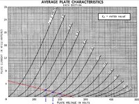
I am just starting to understand how to calculate the Plate and Cathode resistors for a given circuit as well and understanding load lines etc.
IF,
I Understand the math correctly...and that's a big if. Then, in the very first post of this article. the very first tube half of the circuit has 47K plate resistor and a 1.5K (1K5) Cathode resistor. this should equal 5ma of current through the tube. and should also equal about -8v of bias correct??
if that is correct. plotting out the loadline on a tube chart. this should then give a swing of +/- 27.5v with a +/-2v grid change.
The chart i used shows for a -8v bias, the plate voltage will be 172.5v and a +2v swing would drop to 145V and a -2V swing would rise to 200V = 27.5 volts either direction. correct??
this should = 55v P-P or a gain of 13.75 correct?? and 19.44vrms again correct???
Someone, please double check my math here.
I am only looking at the first stage and I am not, for the moment, considering the dynamic load line. I am just trying to make sure i understand the first step of the calculations.
Thanks
Zc
I was re-building my 6SN7 preamp to this configuration (circuit on post #1), and I had a question about the output cap. I currently have a 1uF in this location instead of the 5uF, and was wondering what effect this has on the circuit? So far it sounds really good compared to the original. I get an amplification of about 8.2/8.5 out of this peak to peak using a sine wave, does this sound about right? My B+ is a little low 230V, so I need to tweak my power supply a little.
Thanks for posting this design.
Glenn
Thanks for posting this design.
Glenn
I was re-building my 6SN7 preamp to this configuration (circuit on post #1), and I had a question about the output cap. I currently have a 1uF in this location instead of the 5uF, and was wondering what effect this has on the circuit?
It'll cost you some low frequency performance, as the cutoff will increase. Whether or not that makes a listening difference depends on what you connect to the output, and personal preference.
Thank you Sir. I've got the 4.7uF caps on order, so I'll see if I can tell the difference. It sounds great right now
I'm building this preamp now and I was wondering if I could put some smaller value output caps in as well. Let us know how the bigger caps sound.
I have not compared the two, but built my own design, similar to the 1999 VTV design, back in 1996. Ironically, when I did see the 1999 VTV design, it was almost identical to my design.
A higher plate voltage will bring the tube into a more linear region of the plate curves if the load line is chosen correctly. Unless you need very high voltage output, the two designs probably have similar distortion, but may sound different.
The output coupling cap is small because of the 1 Meg resistor. The combined affect of the RC circuit is a low frequency cut-off of about 0.32Hz. As long as the input stage to your amp is high, the low frequency point will not change too much.
For example, if the input stage to your power amp is 100k, then your low frequency point will move to about 3.39Hz. Still pretty low.
The basic formula for a 6dB per octave frequency cut-off is;
1 / 6.28 (pi times 2) * output resistor * output capacitor (in Farads)= frequency
Cheater Table
10uF = 0.00001F
5uF = 0.000005F
1uF = 0.000001F
0.1uF = 0.0000001F
The output coupling cap is small because of the 1 Meg resistor. The combined affect of the RC circuit is a low frequency cut-off of about 0.32Hz. As long as the input stage to your amp is high, the low frequency point will not change too much.
For example, if the input stage to your power amp is 100k, then your low frequency point will move to about 3.39Hz. Still pretty low.
Thanks THD,
I did find the formulas before and used them for Franks. Sorry for being a little slow. I did the same formula with Franks and with the 100k resistor and 5uf cap the cut-off is still .32hz if I would use a 1uf the cut off would be 1.59hz. I'm sorry but to me these are both well below the range of the music or hearing so why the need for such big caps?
I'm sure I'm just misunderstanding this but if someone could be kind enough to enlighten me. I would be grateful.
By the way I am using a modified Jolida 502 with the volume pot removed and a 6db resistor attenuator in it's place so I believe the input impedance would still be 100k?
As far a I understand it, It an RC Filter. The R is the output impedance of the actual preamp in front of the cap, not the resistor after the cap. So if it is a 1000 output impedance on the pream a 5uf cap, the cutoff would be 32hz Hz, and is no longer a small deal. At 1uf it is 159hz.
Again, you need to know the impedance of the pre...
That 100K resistor on the end of the preamp will be in parallel with amp input impedance.
Again, you need to know the impedance of the pre...
That 100K resistor on the end of the preamp will be in parallel with amp input impedance.
Last edited:
- Home
- Amplifiers
- Tubes / Valves
- Frank’s 6SN7 preamp/linestage