It's all good!
OK, I'm glad that was helpful. I didn't want to come off as lecturing you... And I didn't think the email notification would have all that anyway.
So, since that cat's now out of the bag.... Did your voltages check out? I'm especially interested in the voltage at pin 7 of the EL84. Is that 250V like it says it should be?
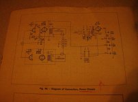
I'm also interested in what that capacitor is doing between B+ and pin 7 of the EL84. Is that a mistake?
--
Hi rongon....no worries much better to be pupil-ed than hectored.
See my last post....checking voltages is now my next order of business How do I do this properly and safely with a multi-meter? Do I stand on a proverbial rubber mat wearing rubber gloves?
As to the cap marked C53 .001uf between PIN 7 of the EL84 and the B+, beats the heck out of me why it's there....I have a second identical chassis (same manufacturer etc) and that cap is also there.
(ANYONE HAVE ANY IDEAS ON THE REASON FOR ITS EXISTENCE IN THIS CIRCUIT?)
Thanks for your guidance and the input of everyone thus far....I'm doing my best but I work slowly by most standards as I wet my feet.
See my last post....checking voltages is now my next order of business How do I do this properly and safely with a multi-meter? Do I stand on a proverbial rubber mat wearing rubber gloves?
There may be experts out there who have more detailed or officially sanctioned procedures than mine, but...
The way I was taught was:
- Make sure the chassis is on a wooden workbench or table, on a non-conductive, not easily flammable surface.
- Prop up or lay down your voltmeter where you can read it, on a stable surface.
- Set the meter to DC volts, AC volts, as appropriate.
- If testing for DC voltages, the black probe from the voltmeter goes to chassis ground. Use a clip lead and clasp the (insulated!) alligator clips on both the black lead's metal probe and the ground point on the chassis. Keep one hand behind your back or in your pocket, not grasping the metal chassis. In your other hand, hold the red probe by the plastic handle and carefully use the probe point to touch the connection where you want to test the voltage.
- If testing for AC voltages (like heaters) the red and black probes go between the two conductors carrying the AC voltage. For instance, red probe on pin 4 and black probe on pin 5 on the EL84's should give you 6.3VAC on the meter. Or, if there's not enough space for getting both probes on those pins without making shorts, put the black probe to chassis ground and put the red probe to pin 4. Should read 3.15VAC (half of 6.3). Then put the red probe to pin 5. Should again read 3.15VAC.
- It's nice to have a plastic or wooden (non-conductive) pointy tool of some kind (pointy chopstick?) to push wires or such out of the way when needed. Don't poke your fingers into a live chassis to move stuff out of the way.
- A rubber backed carpet underfoot is a good idea.
- Wearing sneakers or other rubber soled footwear is a good idea.
Never ever make a short circuit between your two hands. Your heart, lungs and noggin are in the middle between your two arms!
--
Yep...was reading the thread on handling high voltages etc...to acquaint myself with the proper techniques etc....all good advice ron....the things I remembered were one hand in my pocket thing and rubber footwear, carpet/mat and rubber gloves...am somewhat acquainted with inadvertently getting on the receiving end of cap charges...so I definitely don't want to experience the real deal.
The non-conductive chopstick idea for moving wires is also a great reminder...thanks.
Am looking forward to finding out if there are any voltage deviations from spec on this chassis.
Regards, Leon.
...so I definitely don't want to experience the real deal. The non-conductive chopstick idea for moving wires is also a great reminder...thanks.
Am looking forward to finding out if there are any voltage deviations from spec on this chassis.
Regards, Leon.
I'm also interested in what that capacitor is doing between B+ and pin 7 of the EL84. Is that a mistake? --
According to Stefkorn and Bibliophile it is to prevent the EL84 from oscillating.
``Hi devilsindetails
It's a bit hard to make out in that scan but it appears to be conected between anode of output tube and B+ supply.
My best guess would be to stop some high frequency oscillation.
It could have been connected from the anode to ground but would require a higher voltage cap. Maybe done for cost reasons.`` (BIBLIOPHILE)
``Correct! It prevents the EL from oscillating.`` (STEFKORN)
CORRECTION FROM POST#40
"My next step was to replace the two .33uf (400 volt) coupling caps marked C50 (see schematic) and the C32 (SORRY SHOULD READ C52) cap (see schematic) 100uf (25 volt)"
My first action with red plate fault on output tube would be change coupling caps C50 both channels..Then check voltage on cathodes of both channels..
Using Ohms law you can calculate the bias current
voltage on cathode divided by cathode resistor value = current.
Voltage on cathode is between valve and top of C52. That will answer you question about any red plates on the OP tubes..or give anyone here the chance to tell you whats wrong..
If the bias is OK then it could be grid current..
Regards
M. Gregg
Last edited:
Well it appears that with some careful and patient guidance (thanks to Cogsncogs, M.Gregg, bibliophile, Stefkorn, woodturner-fran, fullrangeSr.,hemgjord, DavesNotHere, rongon) the little amp that wouldn't, is now producing clean output
Swapped the red-plating 6BQ5 into the other channel and the problem followed it there..ergo...bad tube? Swapped it for another EL84 and voila no more redplating...so my cap job wasn't the problem...glad to know I can do something right!
Completed the voltage measurements as per rongon's advice...all voltages checked out fine and no nasty (Always good to be reminded about safety especially when troubleshooting frustration seems poised to make one throw caution to the wind)
Connected a variable output CD player and crossed my fingers....finally! Nice clean output from low level to high level output...with normal clipping evident only at extreme high output.
Gave it a full two-hour test drive and all seems well....so the amplifier is obviously ok so I`ll take another stab at the volume pot installation.
Swapped the red-plating 6BQ5 into the other channel and the problem followed it there..ergo...bad tube? Swapped it for another EL84 and voila no more redplating...so my cap job wasn't the problem...glad to know I can do something right!
Completed the voltage measurements as per rongon's advice...all voltages checked out fine and no nasty
(Always good to be reminded about safety especially when troubleshooting frustration seems poised to make one throw caution to the wind)Connected a variable output CD player and crossed my fingers....finally! Nice clean output from low level to high level output...with normal clipping evident only at extreme high output.
Gave it a full two-hour test drive and all seems well....so the amplifier is obviously ok so I`ll take another stab at the volume pot installation.
Last edited:
Houston...we have liftoff!
Had another go at the pot...and success! Thanks to all for their patient descriptions of how I should go at this.
Despite some descriptions of this circuit as very basic I'm quite pleased I have a working example of a little SE amp to play with, tinker and observe the application of tube theory, which is making a whole lot more sense to me now as I trace the wiring, tubes, transformers, etc.
For a $17.00 investment, including the recap, it makes for a very affordable and concrete learning tool...DF96..seems to think this circuit is little more than an old radio set design with little to recommend it for tweaking or modifying...
Any thoughts about the schematic from the rest of you? Anything jump out at you as being worthy of tweaking extra performance out of?
Once again, thanks for indulging a beginner!
Leon
Had another go at the pot...and success! Thanks to all for their patient descriptions of how I should go at this.
Despite some descriptions of this circuit as very basic I'm quite pleased I have a working example of a little SE amp to play with, tinker and observe the application of tube theory, which is making a whole lot more sense to me now
as I trace the wiring, tubes, transformers, etc.For a $17.00 investment, including the recap, it makes for a very affordable and concrete learning tool...DF96..seems to think this circuit is little more than an old radio set design with little to recommend it for tweaking or modifying...
Any thoughts about the schematic from the rest of you? Anything jump out at you as being worthy of tweaking extra performance out of?
Once again, thanks for indulging a beginner!
Leon
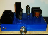
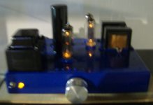
Although there are those who might think my refitting efforts are the equivalent of putting lipstick on a pig..here are a few pics of the little SE amp (my apologies for their quality, my camera calfed on me shortly after the second pic) which I am using as my tube learning tool while I continue with more reading and experimentation.
Thanks to all for their assistance in helping me trouble shoot my volume pot installation.
All is well and I am enjoying this little amp immensely...
Despite whatever limitations or inadequacies others may see in its original design and engineering....it is powering my Wharfedale SFB/3s with ease, no discernible hum and test tones (courtesy of an old Sheffield Studios Test CD)....reveal 40hz-15khz reproduction (the limits of my hearing anyways).
Inevitably this will be a stepping stone to my own, full-out DIY build (RH-84 perhaps)..but I can say without a doubt that learning is a whole lot easier when you have a working example to examine, prod and poke around in (carefully, of course)........
Leon
Thanks to all for their assistance in helping me trouble shoot my volume pot installation.
All is well and I am enjoying this little amp immensely...
Despite whatever limitations or inadequacies others may see in its original design and engineering....it is powering my Wharfedale SFB/3s with ease, no discernible hum and test tones (courtesy of an old Sheffield Studios Test CD)....reveal 40hz-15khz reproduction (the limits of my hearing anyways).
Inevitably this will be a stepping stone to my own, full-out DIY build (RH-84 perhaps
)..but I can say without a doubt that learning is a whole lot easier when you have a working example to examine, prod and poke around in (carefully, of course)........Leon
Attachments
Last edited:
- Status
- This old topic is closed. If you want to reopen this topic, contact a moderator using the "Report Post" button.
- Home
- Amplifiers
- Tubes / Valves
- Forgive me for I have sinned. Help with Volume Pot!