Hi All,
It looks like I am getting very close to having most the remaining bits on the BOM heading my way in November with the final group of parts scheduled for January.
So I am thinking it is about time I ordered me a case.
Unless there is a reason not to, I plan to go with the suggested Dissipante 3U case. But as stated earlier, I am very new to all this and have a couple of questions:
- what extras (like a base plate) are must haves and not just cosmetic?
- is the aluminum upgrade worth it?
- Is there enough room for everything with the 300 mm version or should I go bigger
Any other guidance would be great!
Thank you!
300mm should work good.
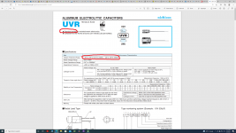
Just got notification from Mouser that the Nichicon UVR1H100MDD - Aluminum Electrolytic Capacitors - Radial Leaded 50volts 10uF 5x11 20% 2LS are out of stock until March 2023. 😲 With the exception of two other parts expected by June, these are the last bits in the BOM needed to build my amp.
@Destroyer OS - Is there an alternative of equal or better quality out there?
The fact I can find them on e-bay for $5 a pop (with $15-$20 shipping) suggests that alternatives are likely hard to find.
@Destroyer OS - Is there an alternative of equal or better quality out there?
The fact I can find them on e-bay for $5 a pop (with $15-$20 shipping) suggests that alternatives are likely hard to find.
Just got notification from Mouser that the Nichicon UVR1H100MDD - Aluminum Electrolytic Capacitors - Radial Leaded 50volts 10uF 5x11 20% 2LS are out of stock until March 2023. 😲 With the exception of two other parts expected by June, these are the last bits in the BOM needed to build my amp.
@Destroyer OS - Is there an alternative of equal or better quality out there?
The fact I can find them on e-bay for $5 a pop (with $15-$20 shipping) suggests that alternatives are likely hard to find.
It can be replaced by literally anything with the same capacitance and voltage. The ammo pack version is in stock. UVR1H100MDD1TA
Thank you all. Not only have I learned what an Ammo pack is, I also learned I should look at Mouser's other sites. ")
I changed my order and to my surprise, after a nearly 1 year wait, the whole BOM shipped! Even cooler, my backordered caps from Parts Connexion shipped yesterday.
Once I get done re-reading all the "how to" threads (and staring at pinnochio's extremely well documented build) I will start stuffing these boards.
Good times ahead!
Okaly Dokaly! I am off to the races.
Started stuffing one amp board today while waiting for my PSU caps to get here. I think I did it all correct but will allow this forum be the judge of that.
Can someone let me know if I got the diode in the correct orientation before I solder it?
If you can see any screw ups, more than suspect soldering that, or if I should be posting this somewhere else... please let me know.
Thank you all for the help.
🙏
I completed the soldering for one channel and have decent hookup wires coming soon. 
So I pieced it all together in hopes I can get the forum to scrutinize my understanding of how this all connects together correctly.
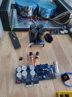
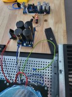
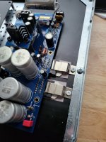
Based on pics I found of other builds and my multiple readings of the build guide, I believe the transformer wires to the PSU this way. They did put tape on one of the wires, so I am assuming I just keep things consistent between the mono-blocks and I should be good (there is no mention as to what that tape means). My second transformer has different colored wires but it is consistent with 2 of the same color to each of the secondary connections.
From what I can tell, one side of the PSU out goes to the chassis ground (represented by a stub of wire with green in the picture). Does it matter what side of the PSU that comes from?
For sanity, is the input cap going to the right holes? It looks like it is obvious, but would hate to find out that I was totally wrong.
Anything look out of order? Am I safe to start building the second channel the same way as the first?
As soon as my soft start board gets here I will mount it all and share a final photo before I plug it in to see if it goes boom. 💥
Thank you everyone for your patience with the clueless guy.
So I pieced it all together in hopes I can get the forum to scrutinize my understanding of how this all connects together correctly.
Based on pics I found of other builds and my multiple readings of the build guide, I believe the transformer wires to the PSU this way. They did put tape on one of the wires, so I am assuming I just keep things consistent between the mono-blocks and I should be good (there is no mention as to what that tape means). My second transformer has different colored wires but it is consistent with 2 of the same color to each of the secondary connections.
From what I can tell, one side of the PSU out goes to the chassis ground (represented by a stub of wire with green in the picture). Does it matter what side of the PSU that comes from?
For sanity, is the input cap going to the right holes? It looks like it is obvious, but would hate to find out that I was totally wrong.
Anything look out of order? Am I safe to start building the second channel the same way as the first?
As soon as my soft start board gets here I will mount it all and share a final photo before I plug it in to see if it goes boom. 💥
Thank you everyone for your patience with the clueless guy.
Attachments
The wiring to psu looks correct. Wiring from PSU to the amp board looks correct.
The power is probably correct as well, as long as one red goes to hot and other to neutral.
As long as you’re in 115-120v country I think everything is working out nicely. Just be really sure the chips are isolated, and the PVI’s put out power.
The power is probably correct as well, as long as one red goes to hot and other to neutral.
As long as you’re in 115-120v country I think everything is working out nicely. Just be really sure the chips are isolated, and the PVI’s put out power.
Finally got everything wired up and ready to go on one channel. I read all the documentation twice, soldered the solder bridge, double checked that the chips were isolated, visually and with my multimeter, from the heat sink and plugged it in.
First I made sure the PSU was working and that checked out so I hooked up the amp, hit the power button, and.... Snap Crackle Pop... I blew up both of the chips. Literally blew them apart. (carnage pic below)
🎆
I am thinking that I must of screwed something up when I bent the chip legs so I could mount the boards to the heat sink like Pinocchio did in his build.
Frustrating, but oh well, I am sure I am not the first person to blow up their amp so have joined that club early. 🥳 I am out of town for a couple of weeks so will not get to try for round 2 till the end of the month. Luckily I bought extra chips so will adjust my strategy back to the traditional ways.
Anything I should worry about after such a catastrophic failure? Nothing else seemed damaged and the power switch got flipped off with the first spark, but I know that really does not mean anything.
Thanks!
-Dan
Attachments
Hi Dan,
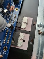
Maybe the chip tab was not proper isolated from the chassis. Did you check for continuity tab to heatsink? There should be none. You should also cleanup the metal around the screw hole, seems like there is metal sticking out. I'm pretty sure this is what caused the issue. Also make sure there is enough pressure contact between the chip thermal pad and heatsink, so that heat dissipates properly. Looking at the pad and screw washer, it seems there wasn not enough pressure.
Do
Hi Pinnocchio,
Thanks for the reply.
That pic is misleading. I am using the suggested clip solution to hold it down which I removed for the carnage pic. I put the clips in place before soldering the chip as well per Jeremy's recommendation.
This blew up as soon as I flipped the power switch so much more likely a short issue.
I checked for continuity using a screw hole I had drilled into the heat sink so there was no paint covering the metal and all the pins as well as the heat sink to tab. That still does not mean I did it right.
Next time I might shoot video of the tests to make sure I am not doing something wrong before flipping the switch.
Attachments
Check all traces and make sure nothing looks blown.
Where did you get chips from? There are counterfeits out there, and they are incapable of parallel operation. Also the chips didn’t have any encasement crumble did they? ( before turn on ). Bending legs shouldn’t be able to cause anything internal unless it broke the encasement some.
Pics are good to help. The ones Do is requesting should help.
I definitely will take extra precautions before I try this again and more pics from underneath.
Chips were from Mouser and digikey (I order the extras when I saw the lead time from Mouser and there was none from the other supplier). The ones that blew up were from digikey.
Attached Pics Include -
I have a couple of weeks before I can get back at it, so that will give me time to re-evaluate my strategy.
I might complete the "un-tainted" board to ensure I am capable of building something that works without worrying about having blown up the traces.
Thanks again for all your attention!
Chips were from Mouser and digikey (I order the extras when I saw the lead time from Mouser and there was none from the other supplier). The ones that blew up were from digikey.
Attached Pics Include -
- The first attached pic was taken while soldering
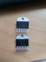
- The second pic has the two different chips and the top chip is from mouser. The bottom one is from digikey. The numbers are a little different but I am assuming those are batch numbers
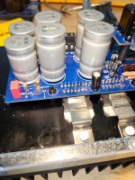
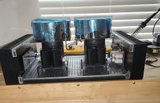
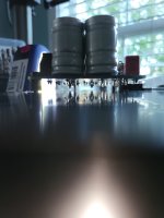
- Third pic is my space saving strategy. If bending legs does not cause the problem, then I might try that again as I have a serious space issue that I am solving by elevating the transformers so they look like cooling towers and freeing up space below. (the base plates will wind up mounted to the chassis and not at the top of the PVC)
- I took the last set of pics while making sure there was nothing touching the heat sink.
I might complete the "un-tainted" board to ensure I am capable of building something that works without worrying about having blown up the traces.
Thanks again for all your attention!
Attachments

Pics were made during soldering. I am on a plane now (actually stuck on a tarmac in seattle), so will need to dig in when when I get back.Did you check PSU polarity? Can we make sure diodes are correct etc?
One chip doesn’t look soldered. Seeing the under board may provide value, see if solder made a bridge or something.
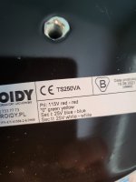
Which model transformers?
Toroidy 250va 25 25 (label can be seen in post #431).
Thank you everyone for the support!
- Home
- Group Buys
- Folsom EC7293: PVI Powered Frontend, 60/120w 8/4ohm